Localization device cross check

a technology of localization device and cross-checking point, which is applied in the direction of radiation beam directing means, instruments, applications, etc., can solve the problems of development of erroneous information and adverse effects of surgical procedures, and achieve the effect of increasing integrity

Active Publication Date: 2010-11-09
AESCULAP AG
View PDF26 Cites 17 Cited by
  • Summary
  • Abstract
  • Description
  • Claims
  • Application Information

AI Technical Summary

Benefits of technology

[0005]The present invention provides a method and apparatus to verify the accuracy of points palpated using a localization device. The aforementioned need is satisfied by obtaining points from a preoperative image of an object to be palpated and, during a surgical procedure, determining the accuracy of palpated points based on the palpated points and corresponding points obtained from the preoperat

Problems solved by technology

If any of these factors are amiss, the pointer tip position as determined by the localization device will be inaccurate, which, in turn, will result in the development of erroneous i

Method used


Image

  • Localization device cross check
  • Localization device cross check
  • Localization device cross check

Examples


Embodiment Construction

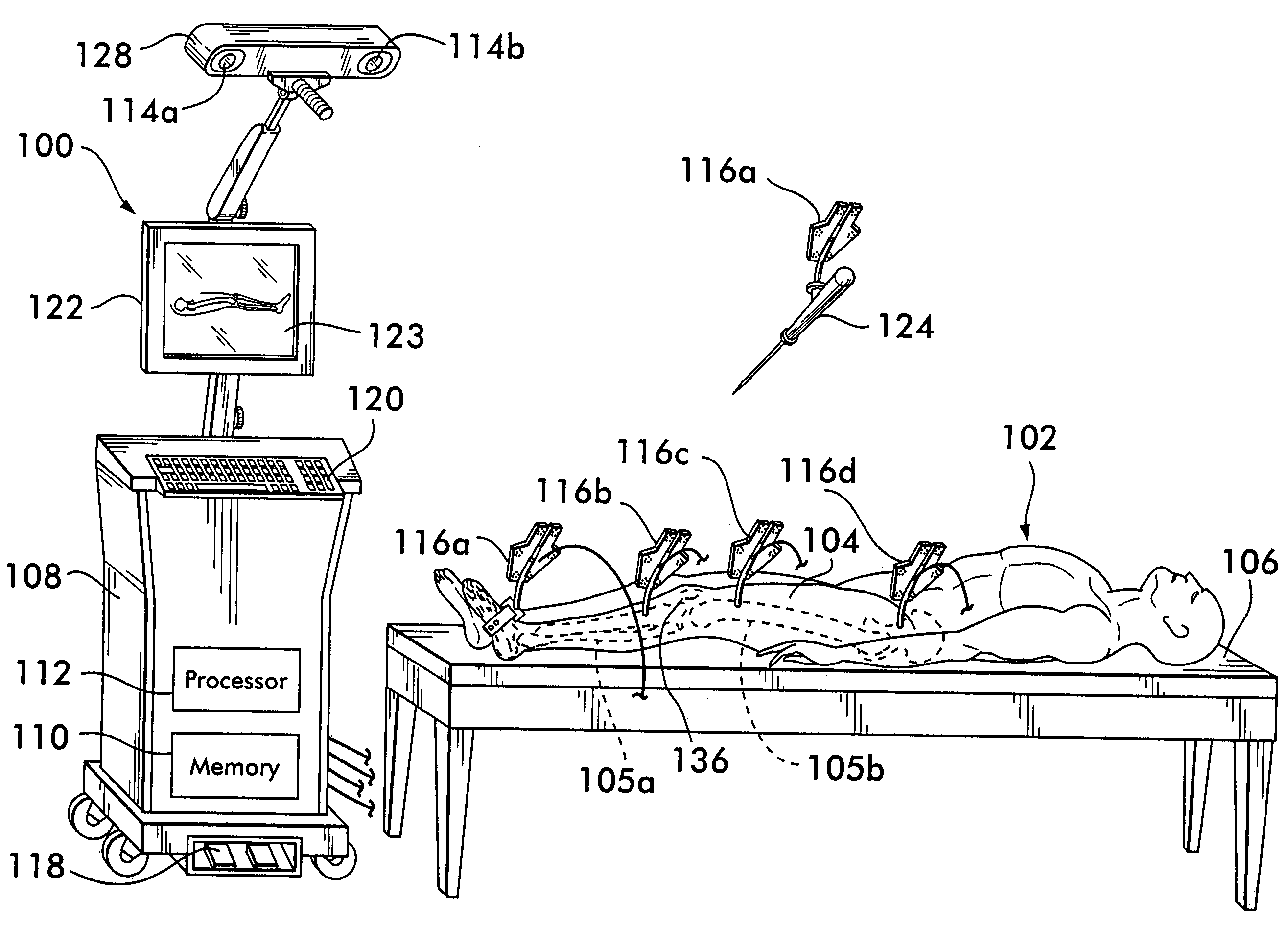
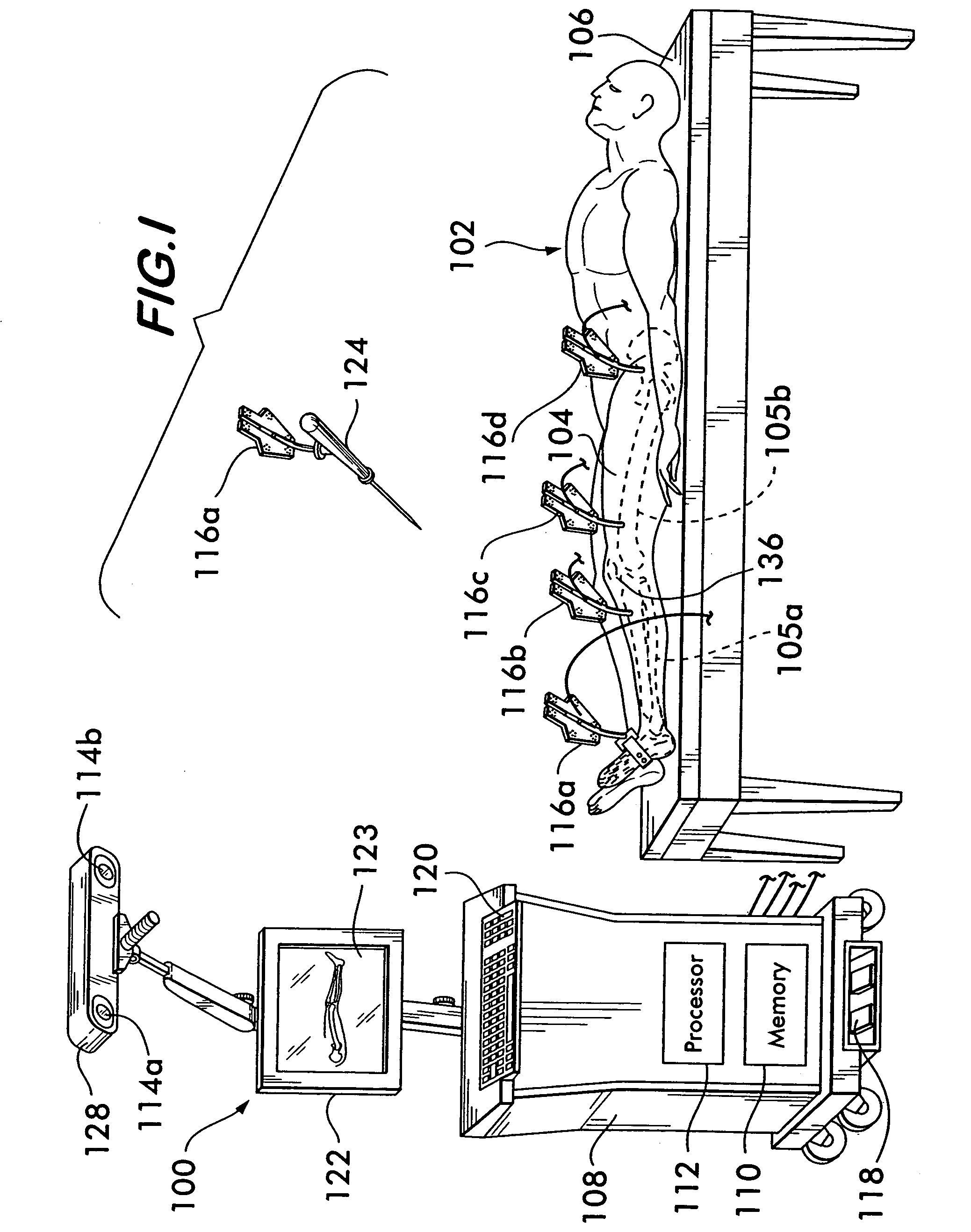
[0016]FIG. 1 depicts a localization device 100 in which the method of the present invention may be employed. In FIG. 1, a patient 102 who is to undergo a surgical procedure on a leg 104, e.g., a Total Knee Arthroplasty (TKA), is illustrated schematically lying on an operating table 106. The localization device 100 includes a computer 108 loaded with software for surgical navigation, a memory 110, a processor 112, sensors (or cameras) 114 capable of detecting markers 116, a foot pedal 118, a keyboard 120, and a monitor 122 with a display screen 123 for displaying surgical navigation information. The display screen 123 is available to a surgeon for guiding the surgeon during surgical procedures performed using the localization device 100. The sensors 114 are positioned above and laterally from the patient 102 so that the patient's leg 104 is in the field of view of the sensors 114. In general, the markers 116 are fixedly mounted on bones (e.g., a tibia 105a and a femur 105b) and surgi...


PUM


Abstract

A method and apparatus for cross checking points palpated with a localization device. Points corresponding to the palpated points are obtained from a preoperative image of an object such as an X-Ray of a tibia bone. During a surgical procedure, the accuracy of palpated points are determined based on the palpated points and corresponding points obtained from the preoperative image. If a palpated point is inaccurate, an indicator is generated to indicate the inaccuracy of the palpated point.

Description

FIELD OF THE INVENTION[0001]The present invention relates to medical instruments and, more particularly, to a method for cross checking points palpated using a localization device.BACKGROUND OF THE INVENTION[0002]Localization devices have been developed to assist surgeons in performing surgical procedures. When utilized in a procedure, markers that can be tracked by a stereoscopic camera system are attached to bones. The stereoscopic camera system is connected to a data processing system that records the positions of the markers in space to establish a coordinate reference system relative to each bone bearing a marker. Additional markers may be attached to surgical tools and the localization device programmed with the location of the working portion of the surgical tool relative to the marker. The tool may then be used to palpate (touch) specific landmarks on the bones while the localization device records their location in order to ascertain the position of the landmarks in the coo...

Claims


Application Information

Patent Timeline
IPC IPC(8): A61B5/05A61B17/34A61B19/00
CPCA61B19/5244A61B17/3403A61B2019/505A61B2019/5238A61B2019/5255A61B2019/5268A61B2019/5272A61B2034/2055A61B2034/2068A61B2034/2072A61B34/20A61B2090/376A61B2034/105A61B2090/0818A61B90/361A61B90/37A61B90/39A61B2090/3916
Inventor FRIEDRICH, DIRKGIORDANO, NICOLALEITNER, FRANCOISTUMMLER, HANNS-PETER
Owner AESCULAP AG
Why Eureka
Try Eureka