Truss gusset plate and anchor safety system

a technology of gusset plate and anchor, which is applied in the direction of girders, building scaffolds, building rescue, etc., can solve the problems of screw and bracket misconnection, incorrect anchor bolt attachment, screw and bracket connection,

Active Publication Date: 2010-11-16
CROOKSTON LAWRENCE A
View PDF36 Cites 13 Cited by
  • Summary
  • Abstract
  • Description
  • Claims
  • Application Information

AI Technical Summary

Problems solved by technology

A problem with these prior art systems is that they rely on a roofing roofer to initially attach the anchor.
This often can result in the anchor being attached incorrectly.
The potential misconnection of anchor bolts, screws and brackets, and the resulting personal injury, is a serious problem with the prior art safety systems.
Additionally, due to the potential liability, building contractors many times retain independent sub-contractors that are expected to provide proper protection, but many times fail to do so.
The difficulty and potential for improper installation lead to disastrous results if a roof roofer should fall, and the need therefore exists for a simple, integrated approach to provide roof safety to every construction site.

Method used


Image

  • Truss gusset plate and anchor safety system
  • Truss gusset plate and anchor safety system
  • Truss gusset plate and anchor safety system

Examples


second embodiment

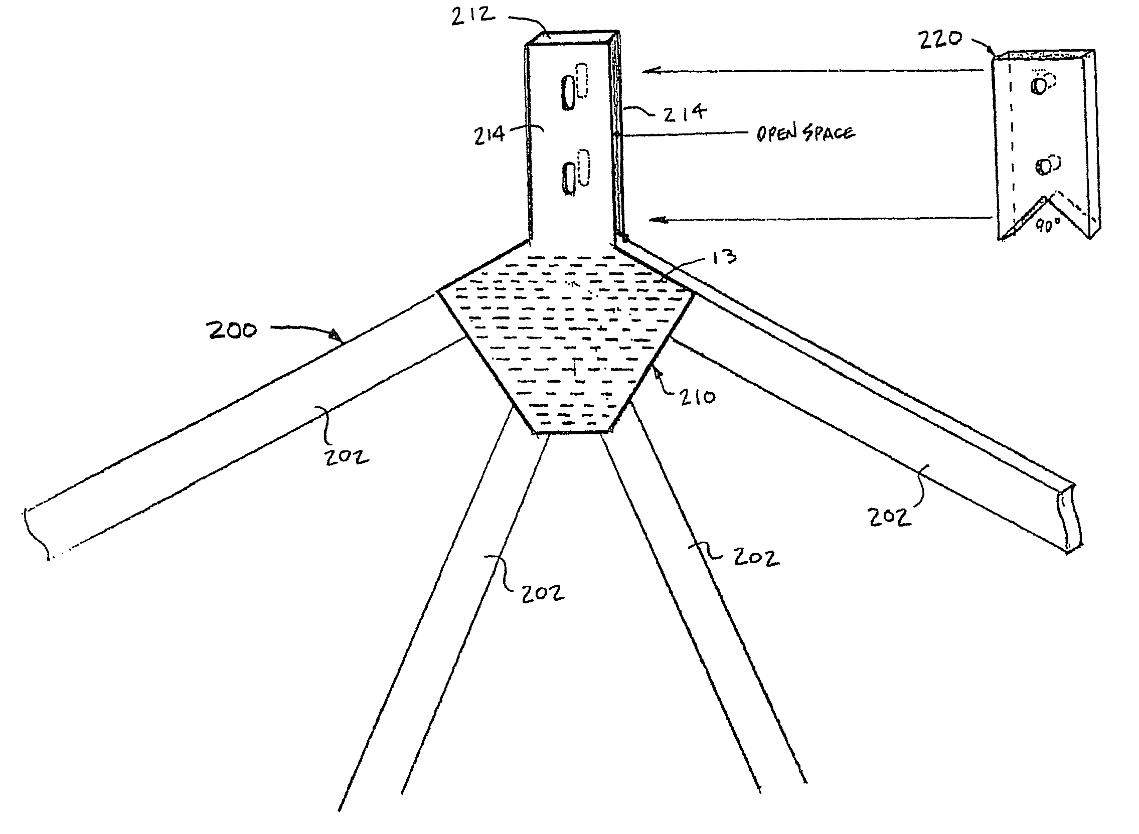
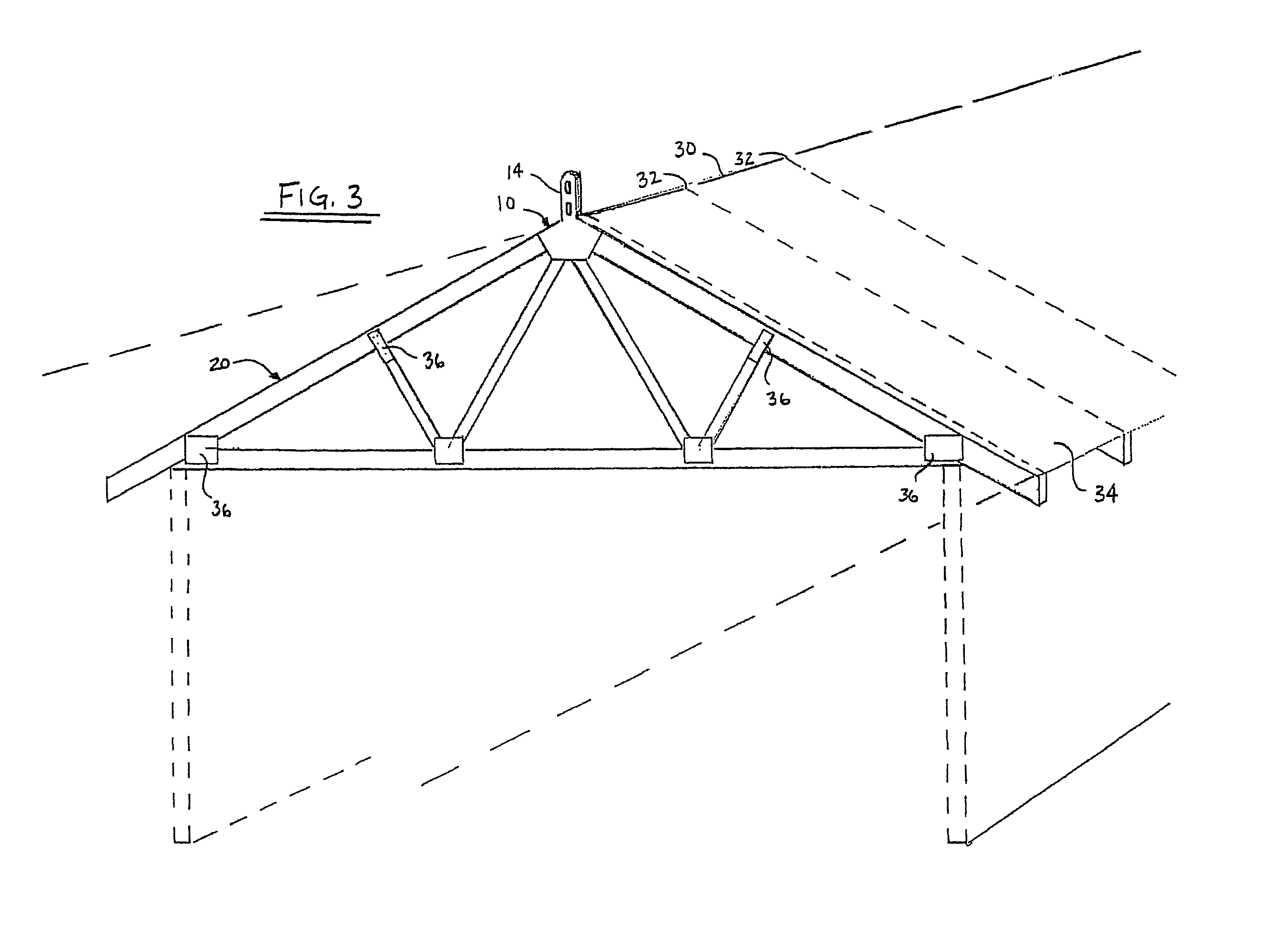
[0075]Referring now to FIGS. 22 and 23, a low profile double peak gusset 710 is shown. Peak gusset 710 is manufactured as one piece and then folded prior to attachment to form truss 700. Double peak gusset 710 comprises a connection portion 712 between the anchor portions 714 of the double gusset 710. A plurality of teeth (not shown) extends perpendicularly from each plate portion 716. A plurality of apertures 725 are formed in the anchor portions 714 and / or the connection portion 712. The double peak gusset 710 is folded on either end of connection portion 712 and attached to form a truss 700 by the plurality of teeth (not shown) engaging the truss member 712 as shown in FIG. 24. Apertures 725 provide an attachment location for a harness cable hook up. As with the previous embodiment, the low profile of the anchor portions 714 and connection portion 712 make it so they can remain in place and simply be covered by the roof peak vent (not shown) or ridge shingles. Alternatively, the ...

first embodiment

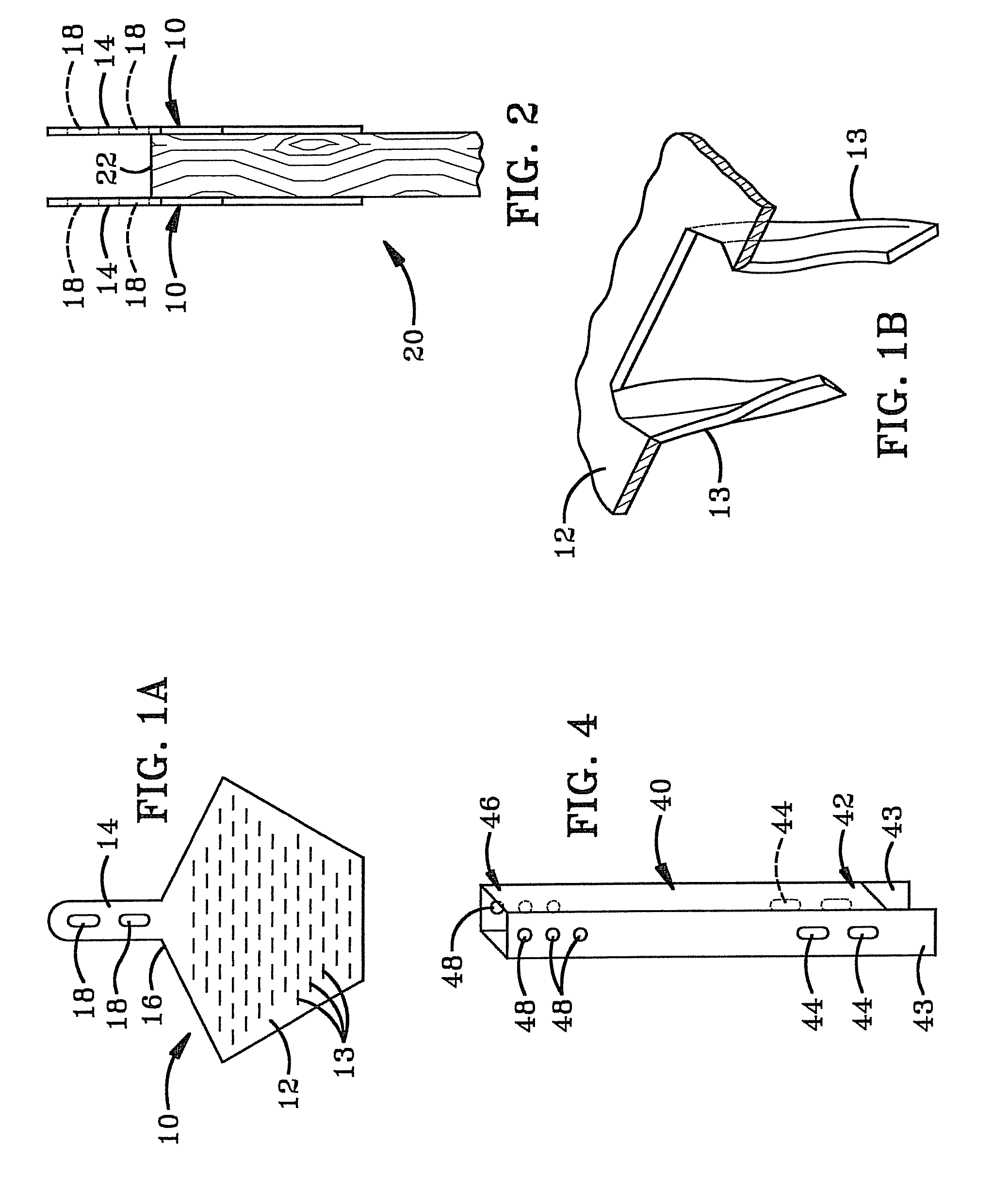
[0093]In accordance with a specific feature of the present invention, gusset plate 1210 includes an attachment region 1228 and an anchor portion 1230 that are generally coplanar with each other. Attachment region 1228 is disposed on the plate adjacent the first and second sections 1210c, 1210d of the first edge and extends for a distance inwardly therefrom and toward the second edge 1210e. Attachment region 1228 includes a plurality of gripping teeth 1211 that project outwardly for a distance from rear surface 1210b and generally at right angles thereto. The number 1236 in FIGS. 49a-52 indicates regions on front surface 1210a that correspond to the regions on the rear surface 1210b where teeth 1211 are located. Teeth 1211 are substantially identical to the teeth 13 of the gusset plate 10 and are shaped so as to be pressed into the wood used to construct a truss 1216. The area of attachment region 1228 adjacent the first edge is substantially triangular in shape and preferably is com...


PUM


Abstract

A gusset connector plate for anchoring a safety line to a roof truss, a roof truss and an anchoring system incorporating the same. The plate is substantially planar and includes an attachment region and an anchor portion. Teeth extend from the attachment region and into the sides of truss members that form the peak of the roof truss. The anchor portion extends laterally beneath the peak and a hole defined therein receives the connector for the security line. The hole is disposed below the lower surfaces of the truss members and vertically beneath the peak. The plate is permanently engaged with the truss. A single plate or a pair of plates may be incorporated in the roof truss and utilized in the anchoring system.

Description

CROSS-REFERENCE TO RELATED APPLICATIONS[0001]This is a Continuation-in-Part of U.S. patent application Ser. No. 12 / 100,122, filed Apr. 9, 2008, which is a Continuation-in-Part of U.S. patent application Ser. No. 11 / 069,819, filed Mar. 1, 2005, now U.S. Pat. No. 7,380,373.TECHNICAL FIELD[0002]This invention relates to a roof truss connector plate and roof anchor safety system and, in particular, to a connector plate having an anchor portion extending downwardly therefrom that allows components of the roof anchor system to be secured to a roof truss. The truss connector plates are factory installed when the roof truss is formed and provide certifiable anchor capacity to the user.BACKGROUND OF THE INVENTION[0003]The need for securing roofing roofers on pitched roofs is well known and is now being required by many government regulations. Many safety systems have been developed to secure roofers, with the majority involving an anchor attached to either a rafter of a truss or to the surfa...

Claims


Application Information

Patent Timeline
Patent Type & Authority Patents(United States)
IPC IPC(8): E04B1/38
CPCE04C3/17E04D13/174E04G21/3261E04G21/3276E04G21/3295
Inventor CROOKSTON, LAWRENCE A.
Owner CROOKSTON LAWRENCE A
Why Eureka
Try Eureka