Scaffold safety apparatus

a safety apparatus and scaffolding technology, applied in the direction of scaffold accessories, safety belts, building scaffolds, etc., can solve the problems of reducing the safety of workers, so as to increase the safety without minimizing productivity

Active Publication Date: 2009-12-29
LANGSMEAD ROGER
View PDF24 Cites 9 Cited by
  • Summary
  • Abstract
  • Description
  • Claims
  • Application Information

AI Technical Summary

Benefits of technology

[0005]The present invention also is directed to a scaffold safety mount that includes a first elongated member having an attachment for securing the first elongated member to a scaffold, a second elongated member, disposed in a direction essentially parallel to that of the first elongated member. The mount also has a device for engaging a safety line, and a cross bar connecting the top section of the first elongated member to the bottom section of the second elongated member. The first elongated member has a length sufficient to have an attachment for securing the member to the scaffold, e.g., a length between about 2 feet (about 61 cm) and about 6 feet (about 183 cm). The second elongated member has a length sufficient to connect to the device for engaging the safety line, e.g., a length between about 2 feet (about 61 cm) and about 6 feet (about 183 cm). The cross bar has a length sufficient to connect the elongated members so that a person using the device, when installed, extends past the innermost portion of the scaffold, and allows one to move across more than one scaffold section without having to disengage, e.g., a length between about 1 inch (about 2.54 cm) and about 12 inches (about 30.5 cm).
[0008]The present invention also pertains to a safety scaffold system. The system includes more than one scaffold safety apparatus, as described herein, and a safety line engaged to the device (e.g., a hook). When the system is installed, the system allows a person to move across one or more scaffold sections without having to disengage the safety line. The safety line is positioned so that the line is secured to the device for engaging the safety line, double looped and secured (e.g., reattached). The safety line is attached to withstand a weight of between about 5000 lbs. (2267.96 kilograms) and about 20,000 lbs. (9,071.85 kilograms). The present invention further includes a harness system (e.g., a harness that is secured to the person, and a lanyard that connects the harness to the safety line) or body-belt system (e.g., a body belt that is secured to the person and lanyard that connects the body-belt to the safety line) for engaging a person to the safety line.
[0016]The present invention has several advantages. The scaffold safety apparatus of the present invention allows for one to be secured while erecting or building a scaffold. It also provides a larger, more accessible work space for the worker, while being tied off or secured. Additionally, the present invention allows one to move across more than one section of scaffold without having to disconnect and reconnect to the safety line, unlike some devices currently on the market. Hence, the present invention increases safety without minimizing productivity.

Problems solved by technology

Various devices have been used to tie-off or secure workers, but many of them are not suitable for erecting or building a scaffold and often have several drawbacks.
For example, some safety devices restrict workers to a work area of one or two square meters which impede or slow down their ability to work efficiently and get the job completed quickly.
Other safety devices prevent workers from moving between sections of scaffold because a lanyard, the cord that connects the harness to the safety device, often gets caught on the scaffold structure or the safety device itself.
Hence, workers create a dangerous situation because, many times, they have to disconnect the lanyard from the safety device, move to the next section of scaffold, and reconnect to a safety device on this scaffold section.
Workers can accidentally fall when moving between sections with such a device, or sometimes they forget to reconnect all together.

Method used


Image

  • Scaffold safety apparatus
  • Scaffold safety apparatus
  • Scaffold safety apparatus

Examples


example 1

Construction of the Safety Scaffold Apparatus

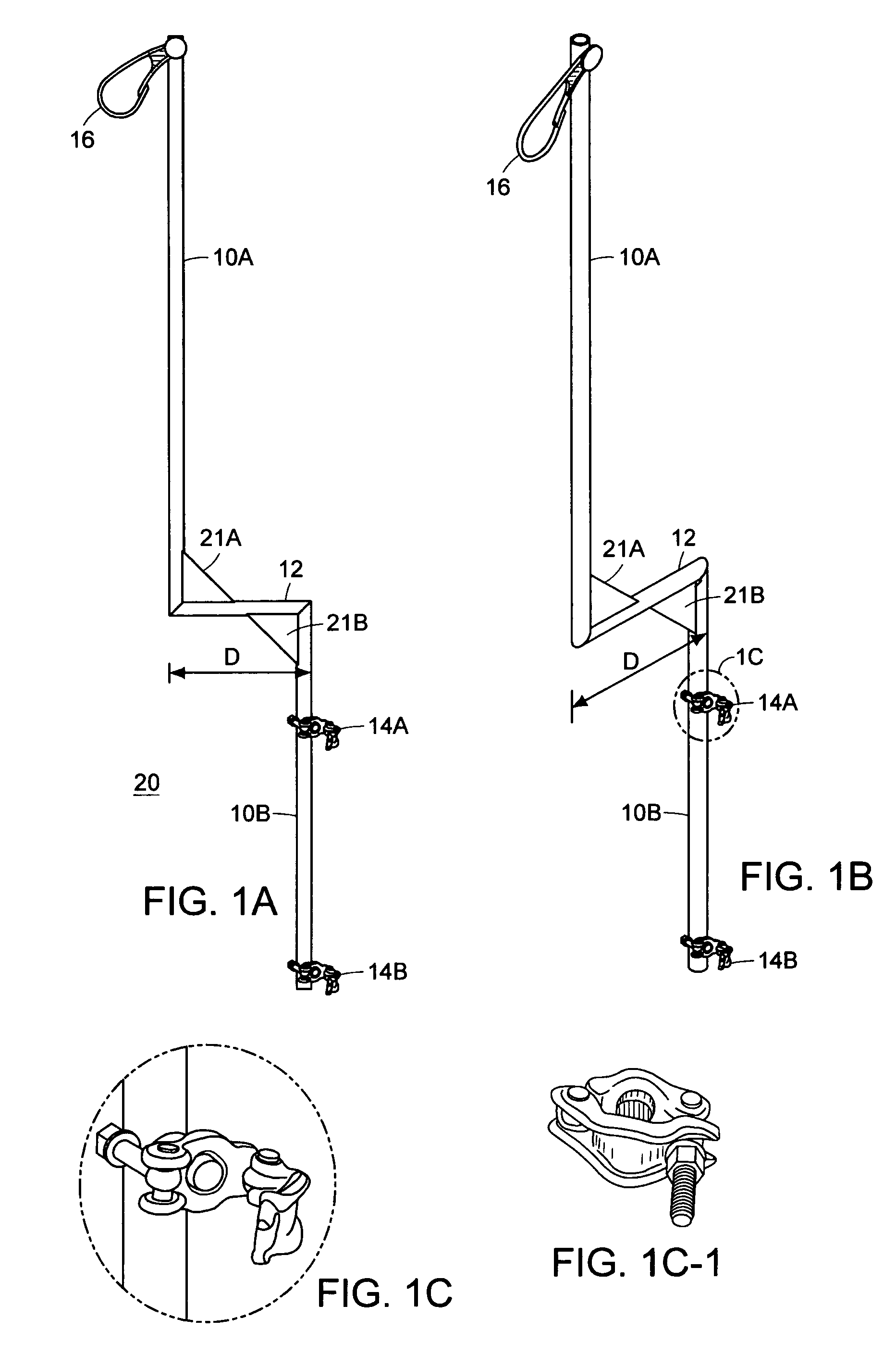
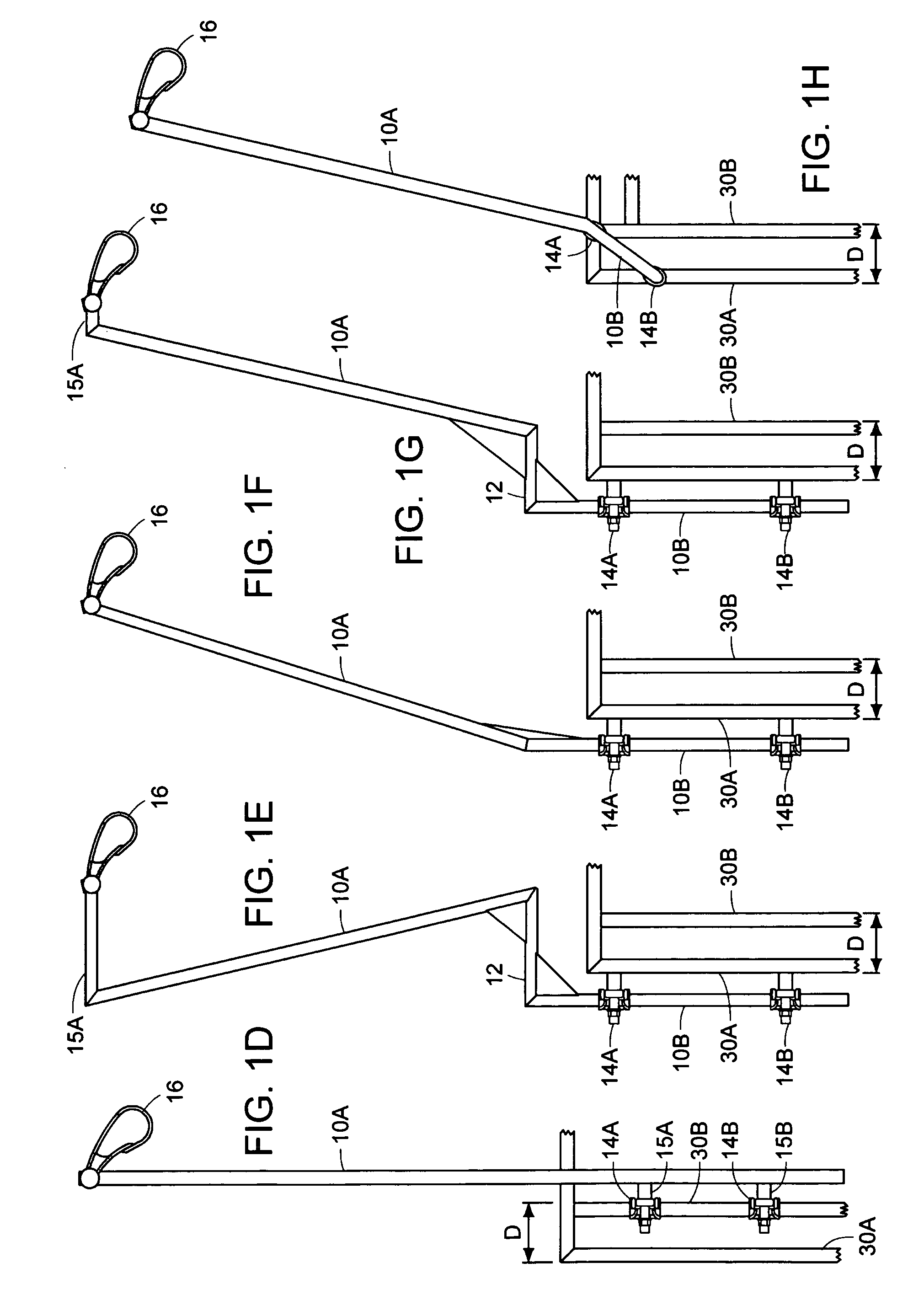
[0057]The apparatus shown in FIG. 1A-C was constructed from two elongated members and a cross bar. These parts were welded together so that the elongated members were essentially parallel. One elongated member has a device for securing a safety line, namely a hook, and the other elongated member has an attachment for securing the safety device to the scaffold, namely two clamps. The elongated members and cross bar were reinforced with diagonal supports. The elongated member having the hook measures about 34 inches, and the elongated member having the clamps is about 32 inches in length. One clamp is positioned about 6 inches from the top of the elongated member, and the other clamp is positioned about 28 inches from the top of the same elongated member. The cross bar is approximately 11 inches in length. The elongated members and cross bar have a diameter of about 1⅝th inches, and are made from steel. The hook, which is about 4 inches in ...

example 2

Use of the Safety Scaffold Apparatus on a Frame & Brace Type Scaffold

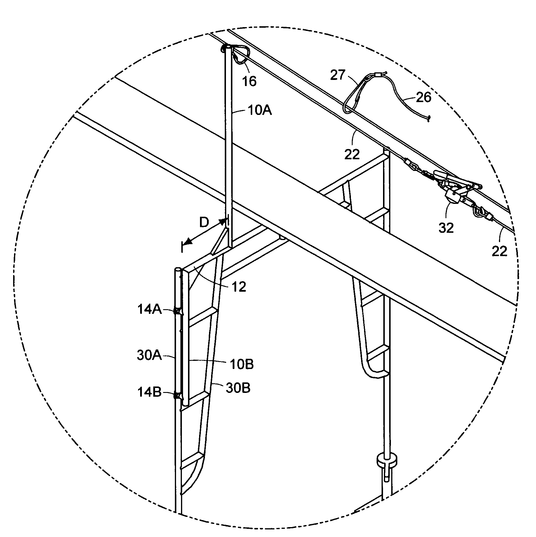
[0058]A series of four apparatuses, constructed as described in Example 1, were installed on a tube and clamp type scaffold (Lynn-Lad Group, LTD. (Lynn, Mass.)). Once the ground level of the scaffold was set-up, each of the apparatuses was clamped to a vertical member of the scaffold, and positioned so that the elongated member having the hook was placed above the scaffold level to which the apparatus was clamped. The hook attached to the elongated member extended past the innermost portion of the scaffold railing underneath, which in this case was the inner railing of the tube and clamp system. The safety line was threaded through each hook and double looped and reattached to itself. The line was tightened and the ends of the line were held in place using a come-a-long device. A person, having a harness and lanyard, then engaged the lanyard hook to the safety line. The person then proceeded to attach the next scaf...

example 3

Use of the Safety Scaffold Apparatus on a Cup Lock Type Scaffold

[0059]A series of four apparatuses, constructed in Example 1, were installed on a cup lock type scaffold (Lynn-Lad Group, LTD. (Lynn, Mass.)). Once the ground level of the scaffold was set-up, each of the apparatuses was clamped to a vertical member of the scaffold, and positioned so that the elongated member having the hook was placed above the scaffold level to which the apparatus was clamped. The cup lock type scaffold does not have a double scaffold railing; rather, it has a single vertical member at each support. Hence, the hook attached to the elongated member extended past the single vertical scaffold railing underneath. The safety line was threaded through each hook and double looped. The line was tightened and secured using a come-a-long device. A person, having a harness and lanyard, then engaged the lanyard hook to the safety line. The person then proceeded to attach the next scaffold level and install the ve...


PUM


Abstract

The present invention relates to scaffold safety apparatuses that allow a construction worker to safely tie-off while erecting a scaffold. The present invention allows the worker to move across one or more scaffold sections without having to disengage the safety line. In one embodiment, the safety apparatus (e.g. safety device or safety mount) includes two offset elongated members disposed in essentially parallel directions, wherein at least one of these two elongated members has a device that engages a safety line. The safety apparatus also has a connector that connects one elongated member to the other elongated member, and an attachment for securing at least one elongated member to the scaffold. The present invention additionally pertains to a scaffold safety system that includes one or more safety apparatuses, and a safety line; safety scaffolds, kits and methods for using same.

Description

BACKGROUND OF THE INVENTION[0001]The U.S. Department of Labor sets out certain criteria to protect construction workers from falling off high area platforms, including scaffolds. For instance, the criteria require, in part, that the workers be tied-off while working on such platforms to prevent accidental falls. Various devices have been used to tie-off or secure workers, but many of them are not suitable for erecting or building a scaffold and often have several drawbacks.[0002]For example, some safety devices restrict workers to a work area of one or two square meters which impede or slow down their ability to work efficiently and get the job completed quickly. Other safety devices prevent workers from moving between sections of scaffold because a lanyard, the cord that connects the harness to the safety device, often gets caught on the scaffold structure or the safety device itself. Hence, workers create a dangerous situation because, many times, they have to disconnect the lanya...

Claims


Application Information

Patent Timeline
Patent Type & Authority Patents(United States)
IPC IPC(8): E04G5/00
CPCE04G5/00E04G5/001
Inventor LANGSMEAD, ROGER
Owner LANGSMEAD ROGER
Why Eureka
Try Eureka