Gas cooled LED lamp

a technology of led lamps and gas cooled lamps, which is applied in the direction of electric lighting with batteries, semiconductor devices for light sources, lighting and heating apparatus, etc., can solve the problems of reducing the performance of led lamps in use, limiting the placement of leds, and limiting the light coming from leds, so as to increase heat transfer and dissipate heat to the gas

Active Publication Date: 2013-11-14
IDEAL IND LIGHTING LLC
View PDF7 Cites 97 Cited by
  • Summary
  • Abstract
  • Description
  • Claims
  • Application Information

AI Technical Summary

Benefits of technology

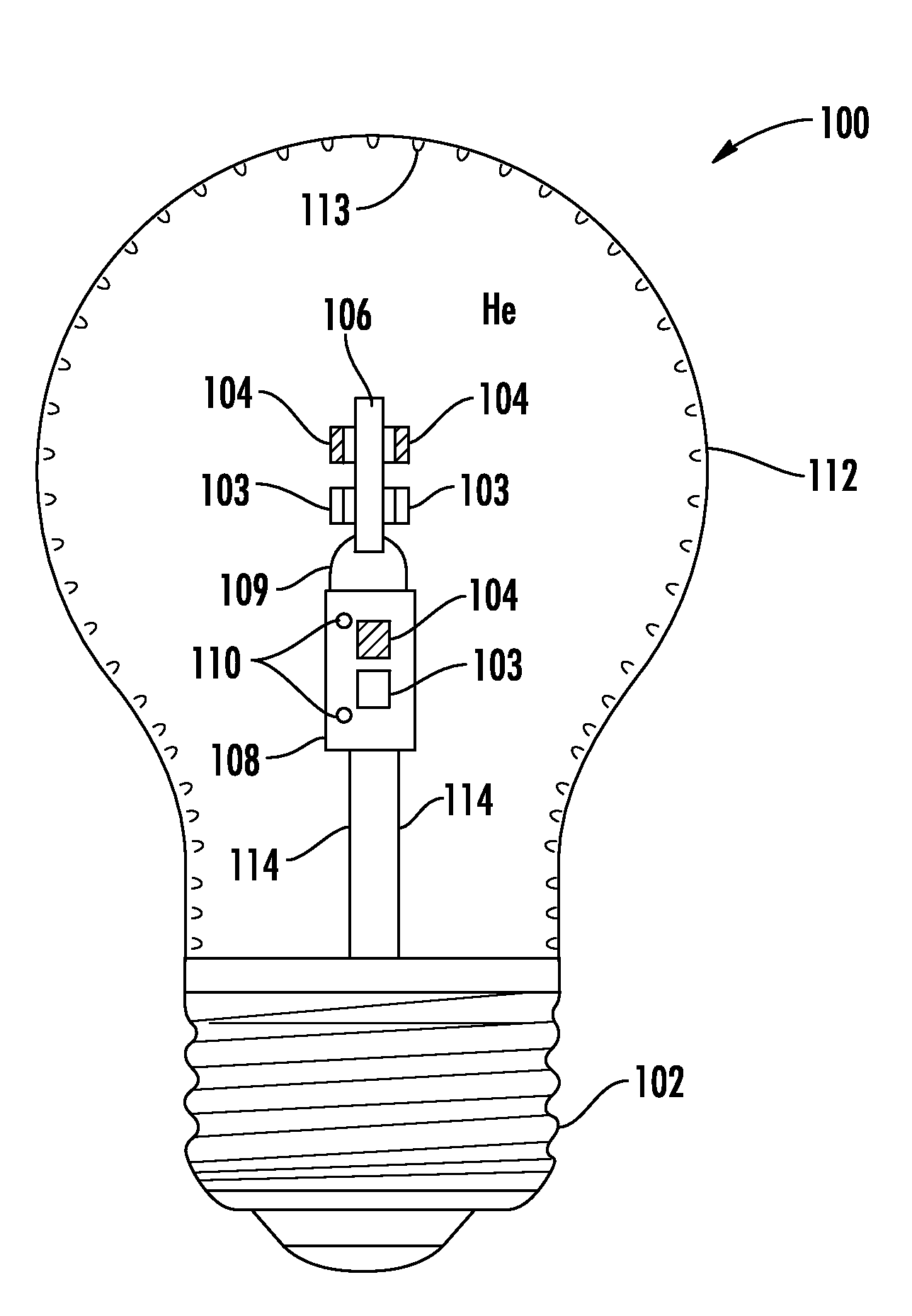
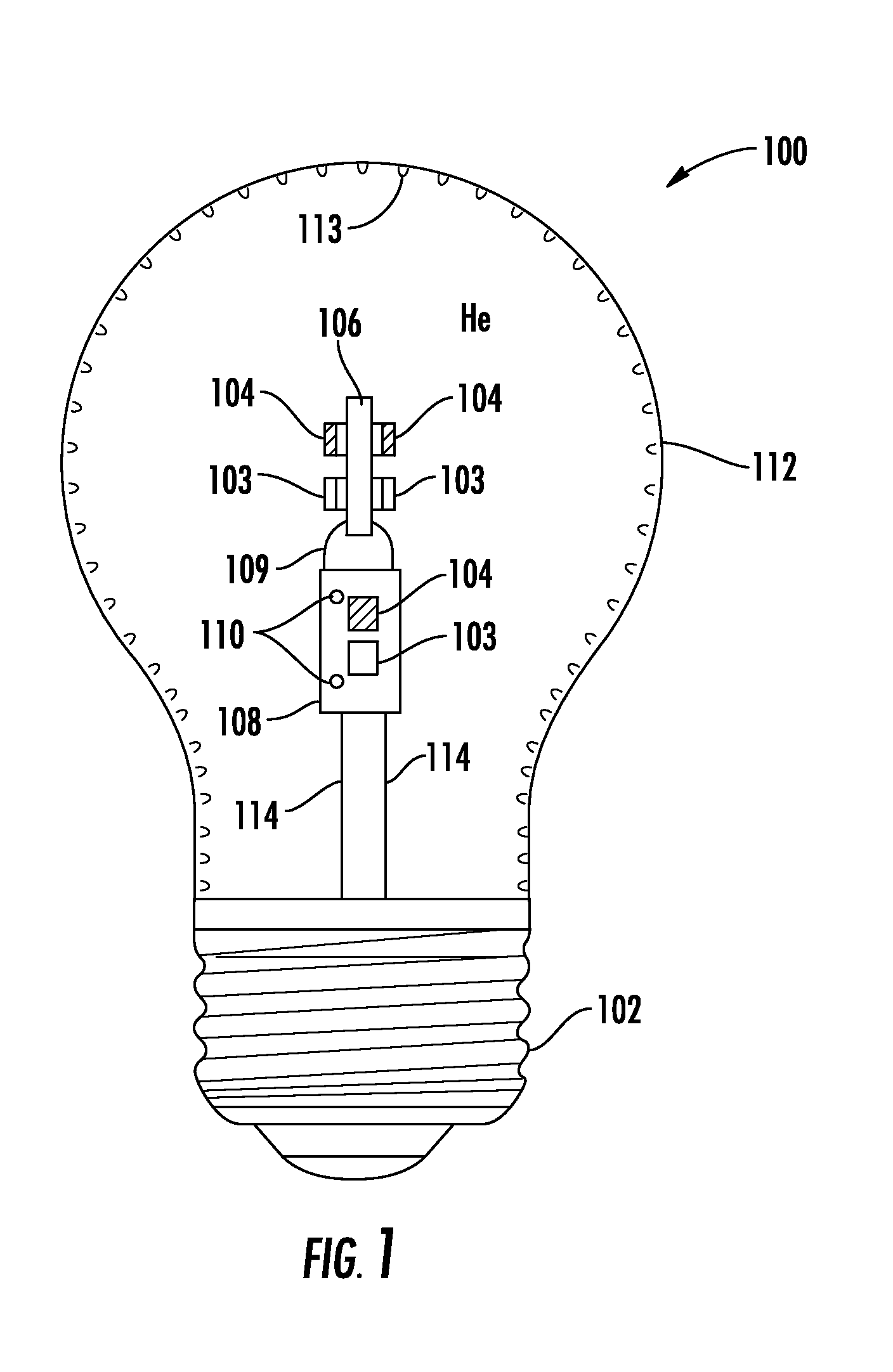
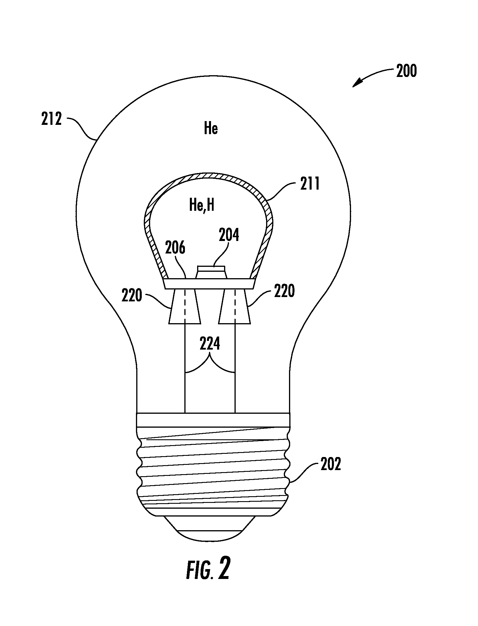
[0009]In some embodiments, the submount may be bendable. The board may be supported in the enclosure by conductors that form part of the electrical connection. The submount may be formed with a first connector and the board may be formed with a second connector where the first connector engages the second connector to secure the submount to the board. The first connector may comprise one of a female connector and a male connector and the second connector may comprise another one of a male connector and a female connector. The first connector may comprise one of a slot and a tab and the second connector may comprise another one of a tab and a slot. The first connector may comprise a slot and a resilient tab adjacent the slot and the second connector may comprise a tab where the resilient tab is deformed by the tab to create a pressure force on the tab. A first electrical contact may be formed on the board that is electrically coupled to a second electrical contact on the submount. The first electrical contact may be electrically coupled to the second electrical contact at a soldered joint. The submount may comprise heat conducting portions that provide suitable surface area and allow air circulation such that heat generated by the plurality of LEDs is transferred to the gas. The heat conducting portions may comprise electrically inactive areas. The submount may comprise a circuitized submount and the plurality of LEDs may be mounted directly to the circuitized submount. The submount may comprise a flex circuit comprised of a thermally conductive material. The flex circuit may be a single sided flex circuit. The flex circuit may be formed into a three-dimensional shape providing a surface for supporting the plurality of LEDs. The plurality of LEDs may comprise surface mount LEDs. The flex circuit may be formed into a generally cylindrical shape having vertical surfaces that support the plurality of LEDs. The flex circuit may constitute at least approximately 90% thermally conductive material. The flex circuit may constitute approximately 99% thermally conductive material. The flex circuit may be flooded with copper to provide enough heat conductive material that heat generated by the plurality of LEDs is dissipated to the gas in the enclosure such that the performance of the LEDs is not degraded. Portions of the flex circuit may form heat conducting elements that provide suitable surface area and allow air circulation such that heat generated by the LEDs is transferred to the gas. An aluminum stiffener may be attached to the back of the flex circuit. The submount may comprise a lead frame where the lead frame supports the plurality of LEDs and forms part of the electrical connection between the board and the plurality of LEDs. The lead frame may be made of a thermally and electrically conductive material. The lead frame may be formed into an electrical circuit. The plurality of LEDs may be populated on the lead frame and reflow soldered to the electrical pads on the lead frame at LED solder joints where the LED solder joints mechanically hold the lead frame circuit together. The lead frame may comprise portions that are provided to increase heat transfer between the lead frame and the gas, the portions being electrically isolated from one another. The submount may not include electrical circuitry such that the submount only physically supports the plurality of LEDs and provides a heat sink for dissipating heat to the gas. The plurality of LEDs may comprise top side contact pads that are electrically coupled by wire bonds. The wire bonds may be of sufficient length that the wire bonds accommodate bending of the submount without breaking. The gas may comprise helium and / or hydrogen.

Problems solved by technology

The power supply and especially the heatsink can often hinder some of the light coming from the LEDs or limit LED placement.
Depending on the type of traditional bulb for which the solid-state lamp is intended as a replacement, this limitation can cause the solid-state lamp to emit light in a pattern that is substantially different than the light pattern produced by the traditional light bulb that it is intended to replace.
However, such an arrangement has been considered to be unsuitable for LED lamp designs because the heat generated during the manufacturing process is known to have an adverse impact on the LEDs.
Heat such as applied during the fusing operation can degrade the performance of the LEDs in use such as by substantially shortening LED life.
The heat may also affect the solder connection between the LEDs and the PCB, base or other submount where the LEDs may loosen or become dislodged from the PCB, base or other submount.
Thus, traditional manufacturing processes and structures have been considered wholly unsuitable for LED based lighting technologies.

Method used


Image

  • Gas cooled LED lamp
  • Gas cooled LED lamp
  • Gas cooled LED lamp

Examples


Embodiment Construction

[0077]Embodiments of the present invention now will be described more fully hereinafter with reference to the accompanying drawings, in which embodiments of the invention are shown. This invention may, however, be embodied in many different forms and should not be construed as limited to the embodiments set forth herein. Rather, these embodiments are provided so that this disclosure will be thorough and complete, and will fully convey the scope of the invention to those skilled in the art. Like numbers refer to like elements throughout.

[0078]It will be understood that, although the terms first, second, etc. may be used herein to describe various elements, these elements should not be limited by these terms. These terms are only used to distinguish one element from another. For example, a first element could be termed a second element, and, similarly, a second element could be termed a first element, without departing from the scope of the present invention. As used herein, the term ...


PUM


Abstract

In one embodiment, a lamp comprises an optically transmissive enclosure. An LED array is disposed in the optically transmissive enclosure operable to emit light when energized through an electrical connection. A gas is contained in the enclosure to provide thermal coupling to the LED array. A board supports lamp electronics for the lamp and is located in the enclosure. The LED array is mounted to the board and LEDs are mounted on a submount formed to have a three dimensional shape. The board is electrically coupled to the LED array and the submount may be thermally coupled to the gas for dissipating heat from the plurality of LEDs.

Description

[0001]This application is a continuation-in-part (CIP) of U.S. application Ser. No. 13 / 774,193, as filed on Feb. 22, 2013, which is incorporated by reference herein in its entirety, and which is a continuation-in-part (CIP) of U.S. application Ser. No. 13 / 467,670, as filed on May 9, 2012, which is incorporated by reference herein in its entirety, and which is a continuation-in-part (CIP) of U.S. application Ser. No. 13 / 446,759, as filed on Apr. 13, 2012, which is incorporated by reference herein in its entirety.[0002]This application also claims benefit of priority under 35 U.S.C. §119(e) to the filing date of U.S. Provisional Application No. 61 / 738,668, as filed on Dec. 18, 2012, which is incorporated by reference herein in its entirety; and to the filing date of U.S. Provisional Application No. 61 / 712,585, as filed on Oct. 11, 2012, which is incorporated by reference herein in its entirety; and to the filing date of U.S. Provisional Application No. 61 / 716,818, as filed on Oct. 22,...

Claims


Application Information

Patent Timeline
Patent Type & Authority Applications(United States)
IPC IPC(8): F21V29/00
CPCF21V29/24F21K9/232F21Y2115/10F21Y2107/00F21Y2107/30F21Y2107/40F21V29/60F21V29/502F21V29/65
Inventor HUSSELL, CHRISTOPHER P.EDMOND, JOHN ADAMNEGLEY, GERALD H.PROGL, CURTEDMOND, MARKATHALYE, PRANEETSWOBODA, CHARLES M.VAN DE VEN, ANTONY PAULPICKARD, PAUL KENNETHREIER, BART P.LAY, JAMES MICHAELLOPEZ, PETER E.ADAMS, ED
Owner IDEAL IND LIGHTING LLC
Why Eureka
Try Eureka