
Intradermal injector

a technology of injector and intradermal injection, which is applied in the direction of intravenous devices, injection needles, other medical devices, etc., can solve the problems of inability to properly provide intradermal injection, difficulty in intradermal injection, and inability to administer intradermal material, etc., to prevent backpressure

Inactive Publication Date: 2012-04-24
ANTARES PHARMA INC
View PDF21 Cites 93 Cited by
  • Summary
  • Abstract
  • Description
  • Claims
  • Application Information

AI Technical Summary

Benefits of technology

The invention is an injector that can deliver substances to the dermis layer of the skin. It includes a chamber for containing the substance, a needle for injecting the substance, and a collar around the needle. The collar has a cavity that allows the substance to be injected and prevents it from flowing out of the skin. The injector also has a mechanism to assist in delivering the substance and a needle that can be retracted. The invention also includes a method for administering substances intradermally, a gas chamber for forcing the substance through the needle, and a plunger for controlling the amount of substance injected. The technical effects of the invention include improved accuracy and efficiency of intradermal injection and reduced pain and discomfort for the patient.

Problems solved by technology

While traditional jet injectors are known for injecting a substance intradermally, they are not capable of properly providing an intradermal injection.
Providing sufficient power for such penetration and then depositing the material to be injected just under the surface skin layer, such as what is required for an intradermal injection is challenging.
An injection weak enough to administer the material intradermally may be so weak that not all the substance is delivered as the skin surface is not completely penetrated by the jet.
Traditional needle injection methods aimed at delivering a substance intradermally also suffer from major shortcomings.
The patient is not comfortable during what seems like a long injection due to the desire to deliver the injected substance slowly to prevent the substance from coming back out of the injection site.

Method used


Image

  • Intradermal injector
  • Intradermal injector
  • Intradermal injector

Examples


Embodiment Construction

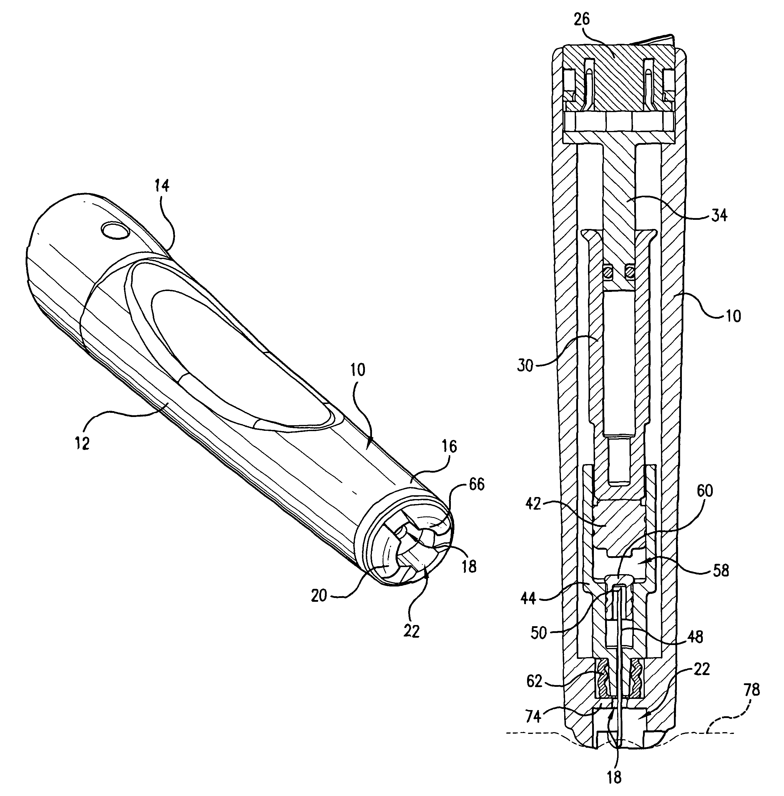
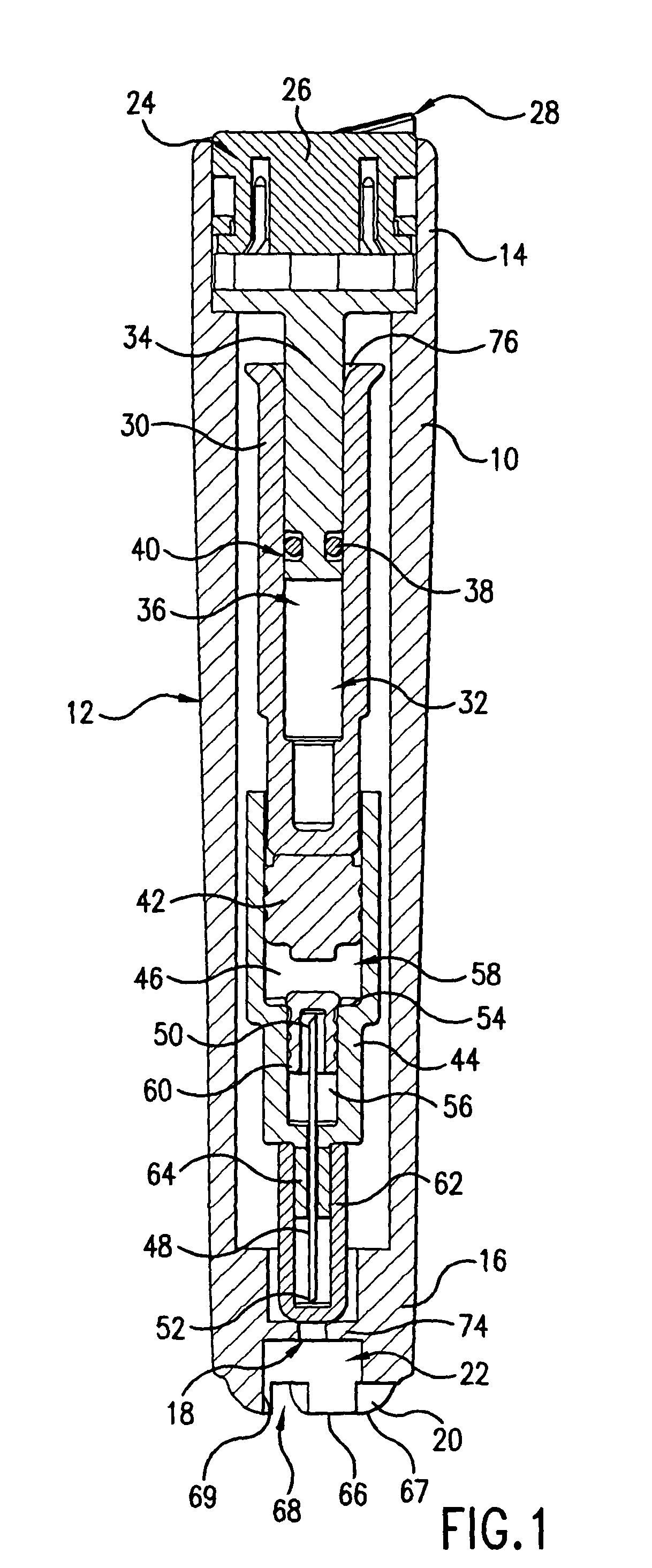
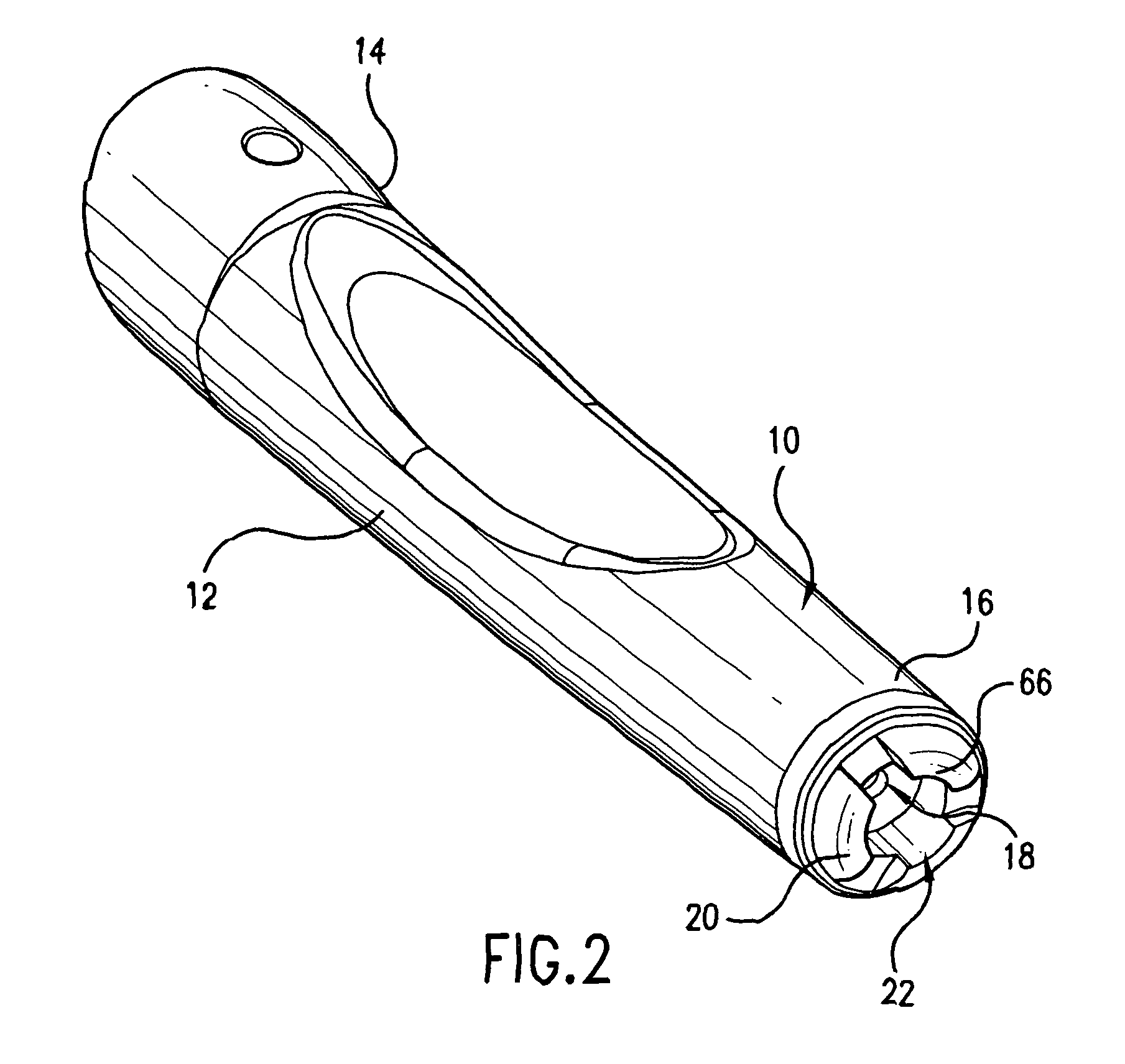
[0016]In the embodiment shown in FIG. 1, the outer housing 10 includes a preferably elongated and cylindrical body 12 with proximal and distal ends 14, 16. As used with respect to the embodiments in this application, the term “distal” designates the end or direction toward the front of injector, and the term “proximal” designates the end or direction toward the rear of the injector. A needle opening 18 is disposed at the forward or distal end of the housing 10 and is configured and dimensioned for receiving an injection needle that extends from the interior of the housing.

[0017]A trigger assembly 24 is preferably disposed at the proximal end 14, although in other embodiments is disposed in other portions of the injector, including at the distal end. The trigger assembly 24 includes a button 26, which is depressible into the housing 10, preferably axially, to fire the injector. The trigger assembly 24 preferably includes a safety lock to selectively prevent the injector from firing. ...


PUM


Abstract

An injection device that comprises a chamber configured for containing a substance to be injected and a needle operatively associated with the chamber and having a length sufficient to deliver the substance to an intradermal injection site. A collar surrounds the needle, defining a collar cavity. The collar also has a peripheral forward skin-contacting surface that surrounds and is radially spaced from the needle and injection site by an area that is sufficiently large to allow a patient's skin to move into the collar cavity to properly position the needle for intradermal delivery of the substance to the injection site to allow spread of the injected substance under the skin while inhibiting or preventing backpressure within the skin from forcing the substance out through the injection site.

Description

CROSS-REFERENCE TO RELATED APPLICATIONS[0001]This application is a continuation of PCT / US03 / 03917 filed Feb. 11, 2003, which claims priority of U.S. Provisional Application No. 60 / 355,926 filed Feb. 11, 2002, the content of which applications is expressly incorporated herein by reference thereto.FIELD OF THE INVENTION[0002]The present invention relates to a injection device. More particularly, the invention relates to an intradermal injector to minimize bubbling or blistering of the skin during injection.BACKGROUND OF THE PRESENT INVENTION[0003]It has been found that intradermal delivery of certain substances and vaccines is more effective than when it is delivered intramuscularly. While traditional jet injectors are known for injecting a substance intradermally, they are not capable of properly providing an intradermal injection.[0004]Jet injectors utilize the stream of the injected substance to overcome the resistance of the skin to penetration. This high velocity stream of substa...

Claims


Application Information

Patent Timeline
Patent Type & Authority Patents(United States)
IPC IPC(8): A61M37/00A61M5/178A61M5/20A61M5/24A61M5/31A61M5/32A61M5/42
CPCA61M5/2033A61M5/425A61M5/3134A61M5/3204A61M5/2046A61M5/2053A61M5/2459A61M5/3202A61M5/326A61M2005/206A61M2005/2073A61M2005/3118A61M5/178A61M5/20
Inventor SADOWSKI, PETER L.LESCH, JR., PAUL R.BREMSETH, DAVID L.
Owner ANTARES PHARMA INC
Learn More