Method for cryogenic cooling of an NMR detection system with the assistance of a container filled with a cryogenic fluid

a technology of cryogenic fluid and detection system, which is applied in the direction of magnetic measurement, gas/liquid distribution and storage, light and heating apparatus, etc., can solve the problems of mechanical vibration transmission into the probe head, easy to interfere, and high installation and operation costs, so as to reduce the consumption of cryogenic liquid, the effect of reducing the effect of vibration transmission

Active Publication Date: 2014-09-25
BRUKER SWITZERLAND AG
View PDF2 Cites 4 Cited by
  • Summary
  • Abstract
  • Description
  • Claims
  • Application Information

AI Technical Summary

Benefits of technology

[0032]Due to the large interior volume VB and the gaseous volume components VG contained therein, any pressure waves in the inflow can be absorbed by compression of the gaseous volume component VG, in particular, because VB is constituted much larger than the associated parameter VZ. In addition, the liquid volume component VL in the container serves as a reserve if, for a short time, the inflow of coolant is insufficient for the quantity of heat to be dissipated. By stocking liquid volume VL, the temperature of the heat source can be kept constant. The generous dimensioning of the outflow conduit prevents back-pressure of the outflow out of the container and thus the occurrence of pressure waves in the conduits and mechanical vibrations. Because the contact element is in close thermal contact with the liquid volume component VL, it is ensured that the heat flow is almost completely transferred by boiling while any heat convection by the gaseous component VG is negligible at the flow velocities of the cryogenic fluid that are typical in an inventive device. In this way, the position and the extent of the heat dissipation is precisely defined and constant over time. Unstable and non-steady flow states in the inflow conduit and the resulting thermoacoustic oscillations that can be expected in the transportation of cryogenic fluids are damped and attenuated in the inventive device and their adverse influence on the NMR signal is minimized. With closed-loop control of the inflow quantity, it is ensured that the state and therefore also the associated advantageous effects remain largely constant in the container.
[0033]In an especially preferred embodiment of the inventive device, the container and the inflow conduit are constituted such that VB>20·VZ, preferably 70·VZ≦VB≦150·VZ applies. These values have proven useful in practice.
[0034]In a further advantageous embodiment, a closed-loop control device is provided that controls the device for setting the inflow quantity of the first cryogenic fluid F1 into the container and controls the volume component VL of liquid cryogenic fluid in the container in relation to the volume component VG of gaseous cryogenic fluid at a definable value. The ratio between VL and VG has a considerable influence on the stability of the cooling and the damping of undesirable vibrations. It is therefore a major advantage to be able to influence this ratio by means of a closed-loop control mechanism.
[0035]It is advantageous if, in the embodiment described above, the closed-loop control device controls the inflow quantity of the first cryogenic fluid F1 into the container depending, in particular, on the heat quantity dissipated from the heat sources through the contact element to the heat exchanger in such a way that VG>VL, preferably VG≧5·VL. These ratios are especially desirable in relation to the properties of the ratio of VG to VL stated above.
[0036]Optimally, the closed-loop control device of the embodiments stated above controls the inflow quantity of the first cryogenic fluid F1 into the container such that F2L≈0. The consumption of cryogenic liquid is thus minimized in a simple manner.
[0037]In an especially preferred variant of the embodiments described above, a temperature sensor is provided to measure the temperature of the heat source whose output signal is fed to the closed-loop control device as an input signal for closed-loop control of the inflow quantity of the first cryogenic fluid F1 into the container. In this way, a constant temperature of the heat source can be simply achieved.

Problems solved by technology

Because the nuclear spin signals are generally very weak, there are easily prone to interference.
Operation of cryocoolers requires a number of items of auxiliary equipment such as compressors, heat sinks, pumps, etc., which makes installation and operation correspondingly costly both in terms of maintenance effort and operating costs.
Moreover, the use of rotating or linearly moving components in the equipment leads to transmission of mechanical vibrations into the probe head.
Mechanical vibrations that are transmitted to the probe head can have a considerable adverse influence on the NMR signal.
Both cooling by evaporation of a fluid cryogen and cooling with cryogenic gases in cryocoolers are used in standard commercial NMR detection systems, although considerable disadvantages are encountered in systems according to the state of the art.
However, such a configuration has considerable disadvantages.
Because the design does not provide for phase separation, the density change affects the liquid phase and the entire fluid transportation in the form of thermoacoustic vibrations.
The cryogenic fluid compressed through the coil under pressure causes vibrations, possibly resulting in susceptibility changes in the coil and mechanical vibrations.
However, the problem of vibrations persists, despite physical separation of the functions “cooling” and “RF reception”, since cryogenic fluid still has to be transported to the heat-conducting connection and the problem of vibrations in the fluid conduits remains.
Because of the flow inlet from below, gas bubbles occurring in the inflow conduit must flow through the entire liquid bath on entering the heat exchanger, resulting in very unsettled bubbling of the liquid level and causing considerable mechanical vibration.
A further weakness is the insufficiently settable or non-settable level of the liquid cryogen and the fluctuating cooling power.
In the case of the device described there, a separate heat exchanger, through which gaseous fluid flows, is used for each coil, which is incompatible with a compact design.

Method used


Image

  • Method for cryogenic cooling of an NMR detection system with the assistance of a container filled with a cryogenic fluid
  • Method for cryogenic cooling of an NMR detection system with the assistance of a container filled with a cryogenic fluid
  • Method for cryogenic cooling of an NMR detection system with the assistance of a container filled with a cryogenic fluid

Examples


Embodiment Construction

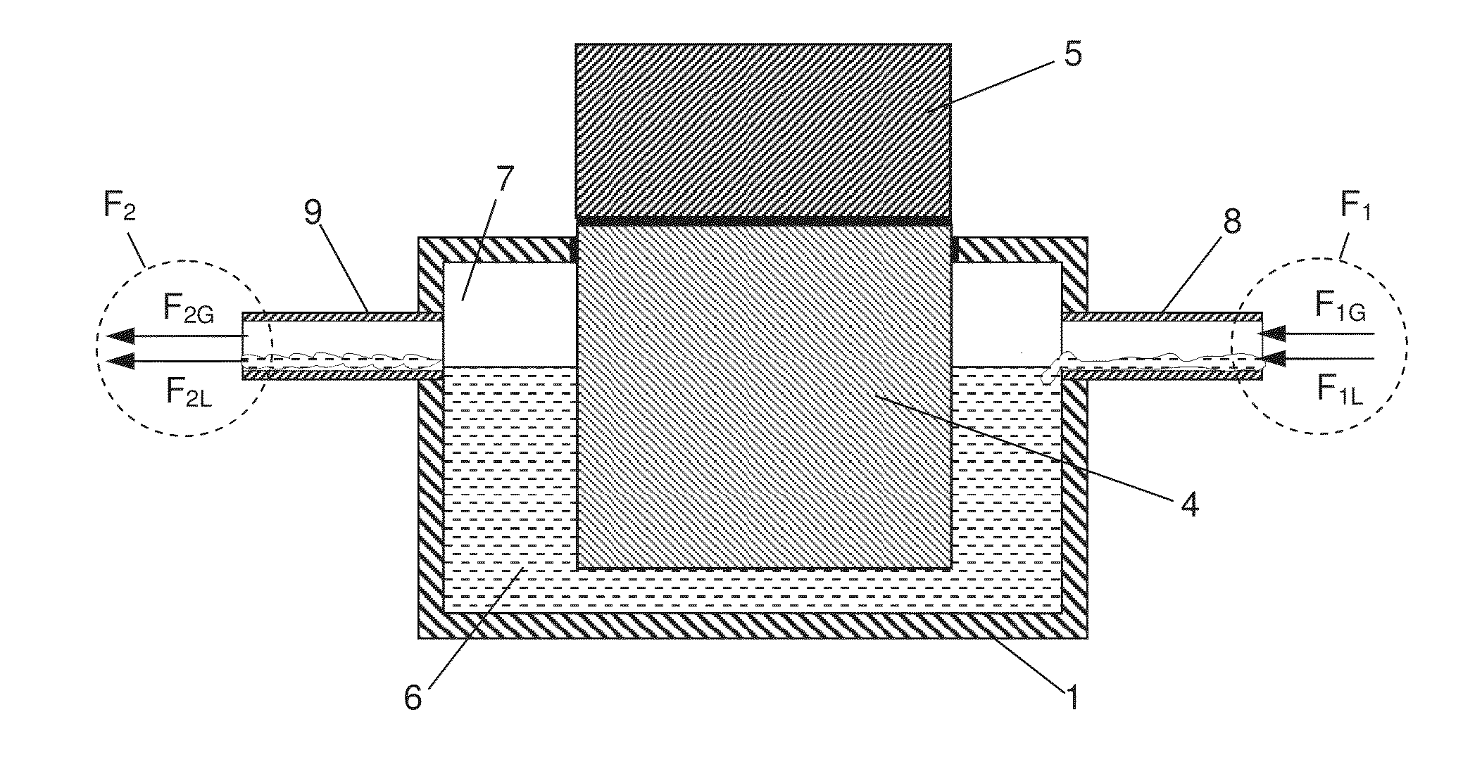
[0072]The inventive method is intended to cool the RF resonator and various components of an NMR detection device to cryogenic temperatures by means of evaporation of a cryogenic fluid, while largely avoiding the influence of vibration that could arise due to excessive boiling of the cryogenic liquid during the cooling operation, which would interfere with the NMR signal. The inventive method also minimizes consumption of the cryogenic fluid.

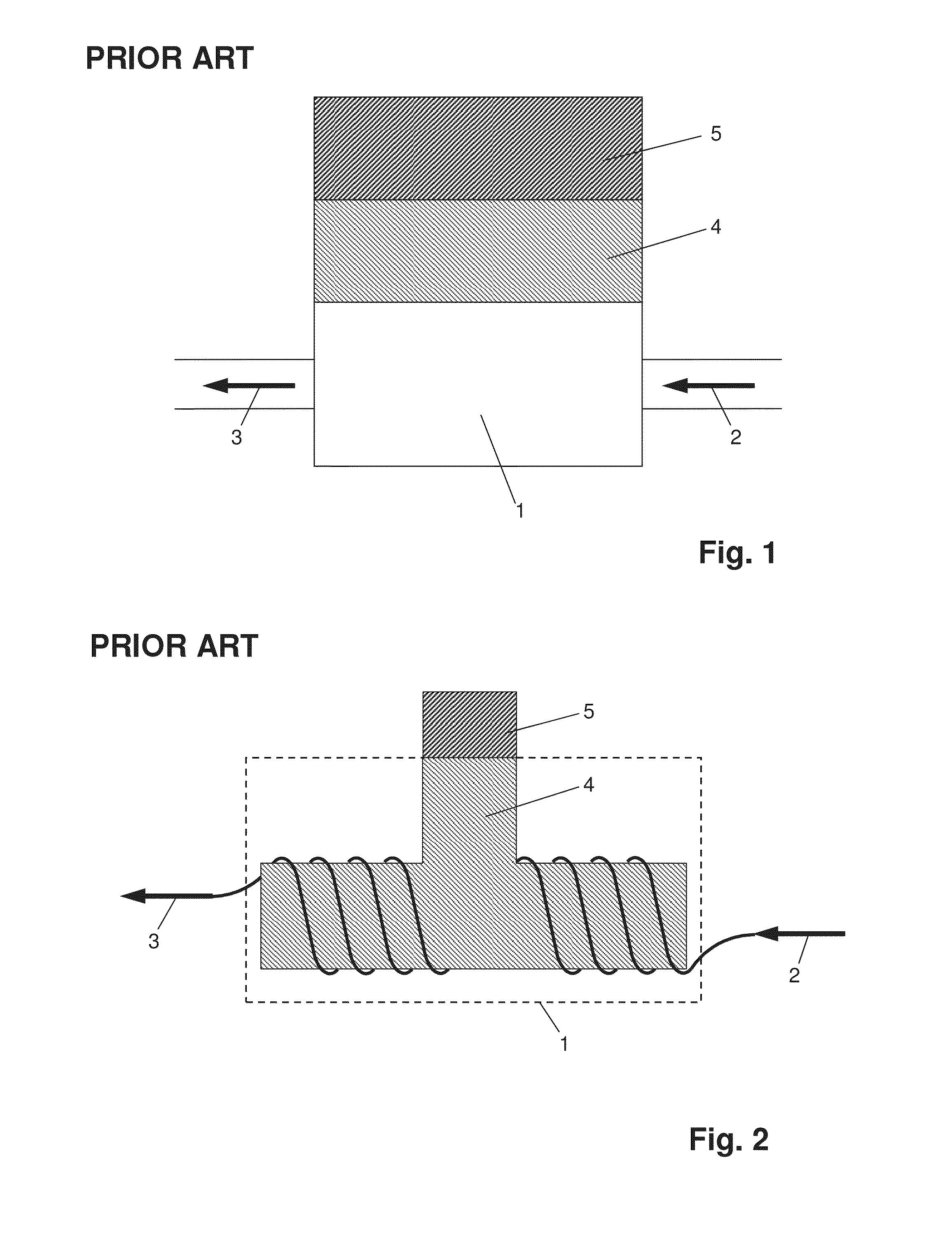
[0073]FIG. 1 shows a heat exchanger according to the prior art with a heat exchanger 1 into which an inflow 2 of coolant flows and from which an outflow 3 of coolant exits. A heat source 5 is connected thermally conductively and permanently to a contact element 4 made of material with good thermal conduction that ensures heat transfer from the heat source to the heat exchanger.

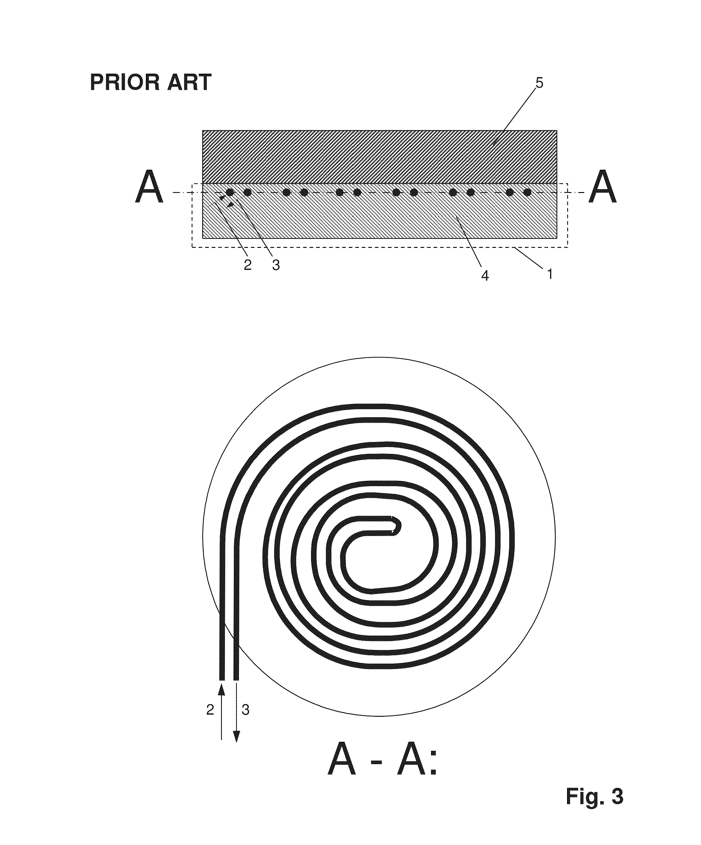
[0074]A further embodiment of the prior art is shown in FIG. 2. Here, the contact element 4 with a T shape is located in the interior of the heat exchanger 1 while the coo...


PUM


Abstract

A method for the transmission / reception of RF signals for NMR measurements uses a heat exchanger (1) for cooling heat sources (5), the heat exchanger having a contact element (4.2) for thermal connection between a cryogenic fluid and the heat source, is characterized in that the heat exchanger comprises a container having an interior volume V.sub.B into which a first cryogenic fluid F.sub.1 that has a liquid component F.sub.1L and a gaseous component F.sub.1G flows through an inflow conduit (8) and from which a second cryogenic fluid F.sub.2 that has liquid component F.sub.2L and a gaseous component F.sub.2G flows out through an outflow conduit (9). The inflow conduit has a flow cross-section Q.sub.Z and a circumference U.sub.Z from which an associated parameter V.sub.Z=4Q.sup.2.sub.Z / U.sub.Z results, wherein V.sub.B>10V.sub.Z, and the outflow conduit has a flow diameter Q.sub.A wherein Q.sub.A.gtoreq.Q.sub.Z. The contact element is in close thermal contact with both the liquid volume component V.sub.L of the cryogenic fluid and with the heat source. A device for setting the inflow quantity of the first cryogenic fluid F.sub.1 into the container is provided that ensures a state F.sub.1L / F.sub.1G>F.sub.2L / F.sub.2G during operation. In this way, vibrations due to the cooling process can be largely reduced and the consumption of cryogenic fluid minimized.

Description

[0001]This application is a continuation of Ser. No. 12 / 926,113 filed Oct. 27, 2010 and claims Paris convention priority from DE 10 2009 046 321.6 filed Nov. 3, 2009, the entire disclosures of which are hereby incorporated by referenceBACKGROUND OF THE INVENTION[0002]The invention relates to a method for structuring and operating a cryo probe head for the transmission and / or reception of radio-frequency signals for nuclear magnetic resonance measurements, with at least one heat exchanger for cooling one or more heat sources, in particular, components of the cryo probe head, wherein a cryogenic fluid is supplied to the heat exchanger and the heat exchanger has at least one contact element that ensures a connection with good thermal conduction between the cryogenic fluid and the heat source.[0003]Such a configuration is known from DE 103 40 352 A1.[0004]In a configuration for measurement by means of nuclear magnetic resonance, a probe head is placed in the strong steady-state magnetic...

Claims


Application Information

Patent Timeline
Patent Type & Authority Applications(United States)
IPC IPC(8): G01R33/34
CPCG01R33/3403G01R33/31F17C2227/0318F17C2227/0395
Inventor SCHNELL, MARC A.PAREDES, MARC ENRIQUECETREFLI, CENGIZSTAUFFENEGGER, PHILIPPEMAREK, DANIEL
Owner BRUKER SWITZERLAND AG
Why Eureka
Try Eureka