One-way valve and automatic intermittent pumping system and method with one-way valve

A one-way valve and valve core technology, which is used in earth-moving drilling, wellbore/well valve device, wellbore/well components, etc. problems, to achieve the effect of simple installation process, digital management, and avoidance of traffic changes

Active Publication Date: 2021-01-29
PETROCHINA CO LTD
View PDF7 Cites 3 Cited by
  • Summary
  • Abstract
  • Description
  • Claims
  • Application Information

AI Technical Summary

Problems solved by technology

[0002] In recent years, in order to meet the coordination of supply and drainage of oil wells and improve the lifting efficiency of rod pumps, intermittent production of pumping units has become an important production method, but the following problems exist in intermittent production: (1) Most of the oil wells on site are not equipped with return valves, There is a risk of liquid backfilling the wellbore in the inter-opening well, and there are certain safety hazards; (2) The existing one-way valve is not suitable for automatic inter-pumping wells, and impurities in the valve cavity are easy to settle and accumulate during use, causing one-way The valve is not closed tightly, and the spring is easily damaged, which leads to

Method used


Image

  • One-way valve and automatic intermittent pumping system and method with one-way valve
  • One-way valve and automatic intermittent pumping system and method with one-way valve
  • One-way valve and automatic intermittent pumping system and method with one-way valve

Examples


no. 1 approach

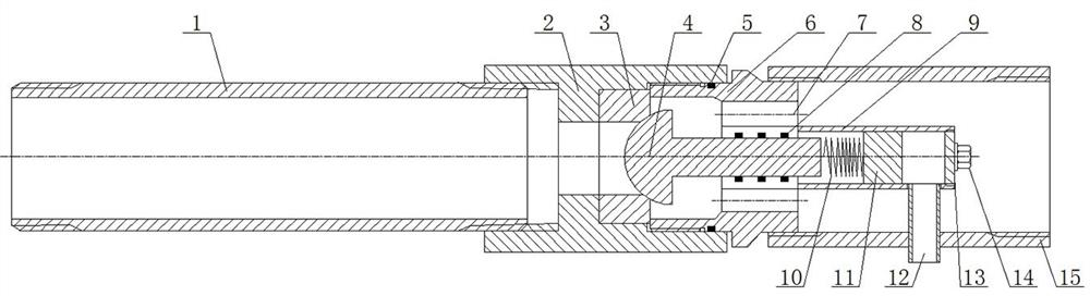
[0032] This embodiment relates to a check valve, see figure 1 , including the upper joint 1, the valve cover 2, the middle joint 6 and the lower joint 15 which are sequentially screwed together coaxially. After being coaxially screwed, it becomes a rotary body structure with an axial hollow channel, and the axial hollow channel of the hollow rotary body supplies oil The liquid flows through, and the valve seat 3, the valve core 4 and the protective sleeve 9 are arranged in the axial hollow passage, wherein the head of the valve core 4 can be contacted and set on the valve seat 3, and the tail of the valve core 4 is fixedly connected to the return spring 10 One end of the return spring 10 is fixedly connected to the electromagnet 11, the electromagnet 11 is placed in the protective cover 9, and the electromagnet 11 slides in the protective cover 9 after electrification and drives the valve core 4 to set or move away from the return spring 10. The valve seat 3 keeps the axial ho...

no. 2 approach

[0038] This embodiment relates to a check valve, see figure 1 , including the upper joint 1, the valve cover 2, the middle joint 6 and the lower joint 15 which are sequentially screwed together coaxially. After being coaxially screwed, it becomes a rotary body structure with an axial hollow channel, and the axial hollow channel of the hollow rotary body supplies oil The liquid flows through, and the valve seat 3, the valve core 4 and the protective sleeve 9 are arranged in the axial hollow passage, wherein the head of the valve core 4 can be contacted and set on the valve seat 3, and the tail of the valve core 4 is fixedly connected to the return spring 10 One end of the return spring 10 is fixedly connected to the electromagnet 11, the electromagnet 11 is placed in the protective cover 9, and the electromagnet 11 slides in the protective cover 9 after electrification and drives the valve core 4 to set or move away from the return spring 10. The valve seat 3 keeps the axial ho...

no. 3 approach

[0051] This embodiment provides a one-way valve, which includes an upper joint 1, a valve cover 2, an intermediate joint 6 and a lower joint 15 which are sequentially screwed together coaxially. The axial hollow channel of the hollow rotary body is used for the oil to flow through. The valve seat 3, valve core 4 and protective sleeve 9 are arranged in the axial hollow channel. The head of the valve core 4 can be contacted and set on the valve seat 3. The valve The tail of the core 4 is affixed to one end of the return spring 10, and the other end of the return spring 10 is affixed to the electromagnet 11. The electromagnet 11 is placed in the protective cover 9, and the electromagnet 11 slides in the protective cover 9 after power-on and passes the reset. The spring 10 drives the valve core 4 to set or move away from the valve seat 3 so that the axial hollow channel is in a blocked state or a smooth state.

[0052] The intermediate joint 6 is a cylindrical structure with two e...


PUM


Abstract

The invention provides a one-way valve and an automatic intermittent pumping system and method with the one-way valve. The one-way valve comprises an upper connector, a valve cover, a middle connectorand a lower connector which are coaxially connected in a screwed mode in sequence. The upper connector, the valve cover, the middle connector and the lower connector are coaxially connected in a screwed mode to form a revolving body structure with an axial hollow channel, and oil liquid flows through the axial hollow channel of the hollow revolving body. A valve seat, a valve element and a protective sleeve are arranged in the axial hollow channel, wherein the head of the valve element can be in contact with the valve seat in a setting mode, the tail of the valve element is fixedly connectedto one end of a reset spring, the other end of the reset spring is fixedly connected with an electromagnet, and the electromagnet is arranged in the protective sleeve. The electrified electromagnet slides in the protective sleeve and drives the valve element to be set or away from the valve seat through the reset spring, so that the axial hollow channel is in a blocked state or a smooth state. Thereset spring can control the opening pressure of the one-way valve, so that the opening pressure is kept within a small range, and flow change and even back pressure backflow caused by overlarge opening pressure are avoided.

Description

technical field [0001] The invention belongs to the field of oilfield exploitation, and in particular relates to a one-way valve and an automatic interval pumping system and method including the one-way valve. Background technique [0002] In recent years, in order to meet the coordination of supply and drainage of oil wells and improve the lifting efficiency of rod pumps, intermittent production of pumping units has become an important production method, but the following problems exist in intermittent production: (1) Most of the oil wells on site are not equipped with return valves, There is a risk of liquid backfilling the wellbore in the inter-opening well, and there are certain safety hazards; (2) The existing one-way valve is not suitable for automatic inter-pumping wells, and impurities in the valve cavity are easy to settle and accumulate during use, causing one-way The valve is not closed tightly, and the spring is easily damaged, resulting in failure of the one-way...

Claims


Application Information

Patent Timeline
IPC IPC(8): E21B34/02E21B34/16
CPCE21B34/02E21B34/16
Inventor 魏小林刘天宇艾信闫娟田殿龙吴利利樊晨于洋李明江操红梅
Owner PETROCHINA CO LTD
Why Eureka
Try Eureka