Hand wheel component of temperature control valve

A technology of temperature control valve and handwheel, which is applied in the direction of valve details, valve devices, engine components, etc., can solve the problems of scattered transmission rods, failure of temperature control valves, and separation of adjustment handles, etc., so as to improve safety, use convenience, Humanized effect of design

Inactive Publication Date: 2011-05-04
卓旦春
View PDF4 Cites 3 Cited by
  • Summary
  • Abstract
  • Description
  • Claims
  • Application Information

AI Technical Summary

Problems solved by technology

The main reason is that the adjusting handle and the handle are connected by threads, but there is no device for limiting the rotation stroke of the adjusting handle, so excessive rotation of the adjusting handle will cause the adjusting handle to break away from the handle, causing the parts to scatter or cause the transmission rod to squeeze Transition of the controlled medium, resulting in failure of the temperature control valve, etc.

Method used


Image

  • Hand wheel component of temperature control valve
  • Hand wheel component of temperature control valve
  • Hand wheel component of temperature control valve

Examples


Embodiment 1

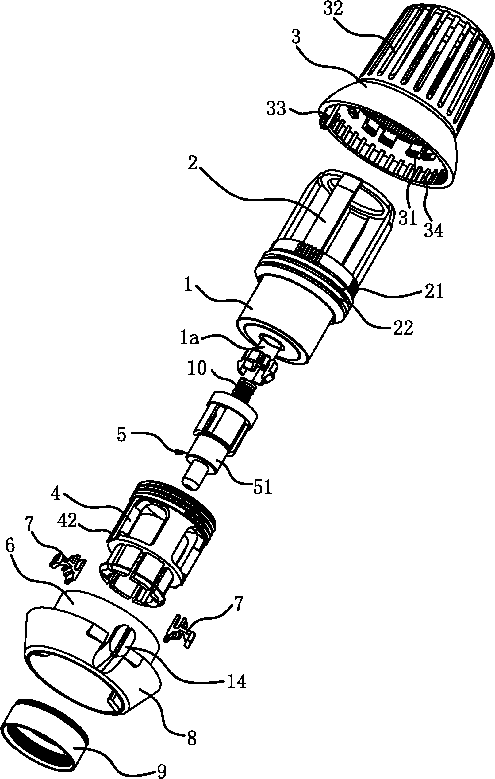
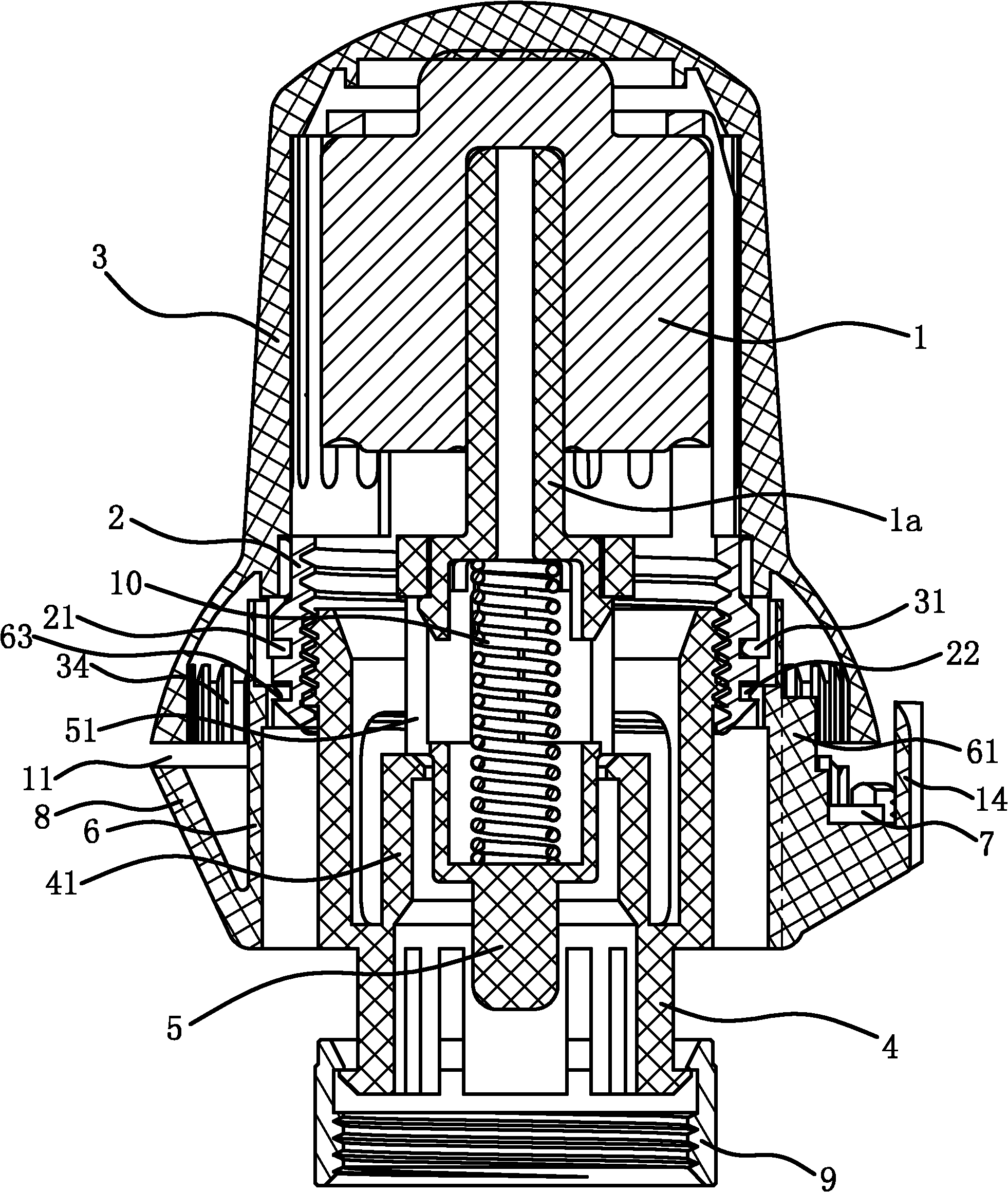
[0038] Such as Figure 1 to Figure 5 As shown, the temperature control valve handwheel assembly includes a temperature bulb 1, a fixing frame 2, a base 4, a housing 3, a limit mechanism and an identification mechanism.

[0039] Specifically, the base 4 is cylindrical, and one end of the base 4 is connected with a nut 9 for connecting the handwheel assembly with the temperature control valve, and the outer wall of one end of the base 4 is threaded.

[0040]The fixed frame 2 is cylindrical, and the temperature bulb 1 is fixed in the fixed frame 2. The opening of the fixed frame 2 and one end of the base 4 are connected by threads, and the free end of the temperature bulb 1 ejector rod 1a can abut against the fixed frame 2. superior. When the fixed frame 2 is rotated, the base 4 moves axially along the inner wall of the fixed frame 2, thereby adjusting the size of the cavity of the temperature bulb 1 for storing the heat-sensitive medium. The outer wall of the fixing frame 2 ha...

Embodiment 2

[0052] Such as Figure 10 to Figure 13 As shown, the structure and principle of this embodiment are basically the same as those of the first embodiment, except that the limiting mechanism includes a stop bar 61 , a stop block 33 and a limit ring 15 . Specifically, the retaining bar 61 is fixed on the outer wall of the base 4, and the stopper 33 is fixed on the inner wall of the bottom of the housing 3, and when the housing 3 is rotated to rotate relative to the base 4, the two sides of the stopper 33 can respectively It abuts against the two side surfaces of the retaining strip 61 in a one-to-one correspondence.

[0053] The limiting ring 15 is sleeved on the base 4 , so the limiting ring 15 can move circumferentially along the outer wall of the base 4 , and can also move axially along the outer wall of the base 4 . The bottom surface of the housing 3 has an annular groove 16, the axis of the annular groove 16 coincides with the axis of the base 4, and one end surface of the ...


PUM


Abstract

The invention provides a hand wheel component of a temperature control valve, and belongs to the technical field of an engineering element, which is used for solving the problem of the existing hand wheel of the temperature control valve that an adjusting handle is separated from a handle dragging component caused by excessive rotation of the adjusting handle. The hand wheel component comprises a thermal bulb, a fixing support and a cylindrical base, wherein, the thermal bulb is fixed in the fixing support; the fixing support is connected with an end part of the base through threads; a post rod of the thermal bulb abuts against the base; the other end of the base is connected with a nut; a shell is fixed outside the fixing support; a limit mechanism for limiting the rotation angle between the shell and the base and adjusting the size of the limited angle is arranged between the shell and the base; and an identification mechanism capable of identifying the circumferential position of the shell relative to the base is also arranged between the shell and the base. The hand wheel component of the temperature control valve has the advantages of accurate control of the rotation stroke range and safe use.

Description

technical field [0001] The invention belongs to the technical field of engineering components, and relates to a temperature control valve, in particular to a temperature control valve hand wheel assembly. Background technique [0002] The heating system is an essential infrastructure in cities in the north and south high latitudes, and it can keep citizens warm and comfortable in winter. The thermostatic valve is one of the important components in the heating system; it is a flow regulating valve. Its basic principle: by controlling the heat exchanger, heat dissipation equipment, and the inlet flow of primary heat medium, the outlet temperature of the equipment can be controlled. When the load changes, the flow is adjusted by changing the opening degree of the valve to eliminate the influence caused by the load fluctuation and restore the temperature to the set value. [0003] The relevant literature on the temperature control valve is a self-operated temperature control v...

Claims


Application Information

Patent Timeline
Patent Type & Authority Applications(China)
IPC IPC(8): F16K31/60F16K37/00
Inventor 卓旦春
Owner 卓旦春
Why Eureka
Try Eureka