Harmonic reject mixer with active phase mismatch compensation in the local oscillator path

Active Publication Date: 2013-06-11
RAYTHEON CO
View PDF4 Cites 24 Cited by
  • Summary
  • Abstract
  • Description
  • Claims
  • Application Information

AI Technical Summary

Benefits of technology

[0011]Amplitude and phase mismatch in the LO path can come from a number of areas, including: layout differences, passive component tolerances, and LO generation method [see N. Moseley, et al., “A Two-Stage Approach to Harmonic Rejection Mixing Using Blind Interference Cancellation,”IEEE Transactions on Circuits and Systems-II: Express Briefs. Vol. 55, No. 10, pp. 966-970. 2008]. Most designs try to minimize the mismatch with good layout practices or by increasing the size of the devices so that mismatch constitutes a smaller percent of the device's total area. These methods are sensitive to process variation, require more area and more DC and LO power to drive the devices. These methods are also usually limited to around 40 dBc of harmonic rejection [see S. Lerstaveesin, et al., “A 48-860 MHz CMOS Low-IF Direct-Conversion DTV Tuner,”IEEE Journal of Solid-State Circuits. Vol. 43, No. 9, pp. 2013-2024. 2008]. Other methods of phase/gain LO mismatch compensation have been proposed that use either digital or analog compensation in the signal path [see N. Moseley, et al., “A Two-Stage Approach to Harmonic Rejection Mixing Using Blind Interference Cancellation,”IEEE Transactions on Circuits and Systems-II: Express Briefs. Vol. 55, No. 10, pp. 966-970. 2008 and H. Cha, et al., “A CMOS Harmonic Rejection Mixer with Mismatch Calibration Circuitry for Digital TV Tuner Applications,”IEEE Microwave and Wireless Components Letters. Vol. 18, No. 9, pp. 617-619. 2008]. The analog compensation method uses adjustable resistors in and between the signal paths before the summing at the output of the mixer. These programmable resistors adjust small amounts of gain mismatch to improve the harmonic rejection. The digital method uses sensors and a digital algorithm to generate a cancellation signal through a digital to analog converter, and combines the error signal with the mixer output to minimize the interference.
[0012]The inventors have recognized that better harmonic rejection in the mixer can be achieved by using a phase rotator to provide small amounts of phase and gain adjustment in the LO path. The phase rotator can produce large shifts in phase in addition to fine tuning, which makes it useful to provide the necessary 45 and 90 degree phase shifts as well. Finally, the phase rotator can

Problems solved by technology

A significant problem with the compressed LO is the odd harmonic content which will mix with the desired signal and create stray signals at

Method used


Image

  • Harmonic reject mixer with active phase mismatch compensation in the local oscillator path
  • Harmonic reject mixer with active phase mismatch compensation in the local oscillator path
  • Harmonic reject mixer with active phase mismatch compensation in the local oscillator path

Examples


Example

[0032]Like reference symbols in the various drawings indicate like elements.

DETAILED DESCRIPTION

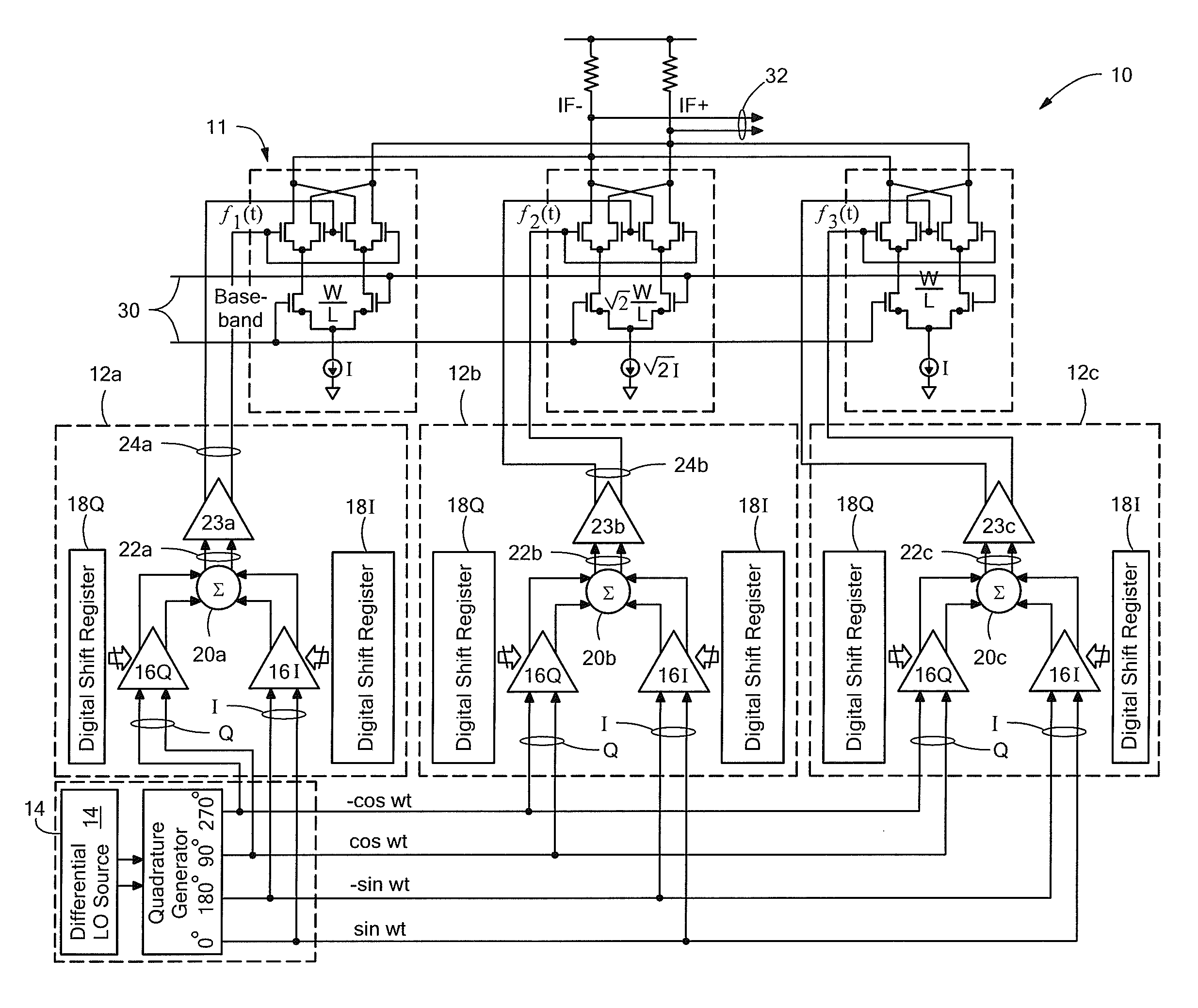
[0033]Referring now to FIGS. 8A and 8B, a harmonic reject mixer 10 with phase rotators in the LO path is shown having: a plurality of, here three, phase rotators 12a-12c fed by a common input local oscillator (LO) 14 signal (here a quadrature signal produced by passing a differential signal from a LO source through a quadrature generator) having a reference frequency. Thus, four signals are produced by the LO 14 each being the same frequency and shifted in phase one from the other by ninety degrees; i.e., .a zero degree phase shift signal (0); a ninety degree phase shift signal (90); a one hundred eighty degree phase shifted signal (180) and a two hundred seventy degree phase shifted signal (270), as indicated The a zero degree phase shift signal (0) and the ninety degree phase shift signal (90) are in the in-phase channel (I) and are fed to a variable gain digital amplifier 161 while the...


PUM


Abstract

A harmonic rejection mixer having a phase rotator fed by a local oscillator signal. The local oscillator signal has a reference frequency. The phase rotator produces a plurality of output signals, each one of the signals having a common frequency related to the reference frequency and having different relative phase shifts. A plurality of mixer sections, each one of the sections being fed an input signal and a corresponding one of the plurality of output signals mixes the local oscillator signal with the corresponding one of the plurality of output signals fed thereto. A combiner combines the mixer signal from the plurality of mixer sections into a composite output signal. A detector detects energy in a harmonic of the composite signal and for adjusting the output signal of the phase rotator to reduce the selected harmonic of the composite signal.

Description

TECHNICAL FIELD[0001]This disclosure relates generally to harmonic reject mixer and more particularly to harmonic reject mixer having active phase mismatch compensation in the local oscillator path.BACKGROUND AND SUMMARY[0002]As is known in the art, switching mixers are frequently used in RF design, and in order to make the switches turn on and off quickly and cleanly these mixers are frequently driven with a large local oscillator (LO) signal such that the signal is compressed. More particularly, the LO signal is a square wave or a very large sinusoidal signal, such that the input voltage swing is larger than the linear region of the transistors. Once the linear region of the transistor is exceeded, the voltage swing will be compressed and appear more like a square wave as the odd-order harmonics increase in power.[0003]A significant problem with the compressed LO is the odd harmonic content which will mix with the desired signal and create stray signals at the output of the mixer....

Claims


Application Information

Patent Timeline
IPC IPC(8): H03D13/00
CPCH03D7/1441H03D7/1458H03D7/1483H03D7/165H03D2200/0086
Inventor MORTON, MATTHEW A.COMEAU, JONATHAN P.THOENES, EDWARD WADE
Owner RAYTHEON CO
Why Eureka
Try Eureka