Sliding bearing element

A sliding bearing and component technology, applied in the field of sliding bearing components, can solve problems such as sliding surface damage and efficiency loss, and achieve the effect of avoiding pressure difference

Active Publication Date: 2021-02-19
MIBA SINTER AUSTRIA
View PDF16 Cites 0 Cited by
  • Summary
  • Abstract
  • Description
  • Claims
  • Application Information

AI Technical Summary

Problems solved by technology

The consequence is a loss of efficiency and especially damage to the sliding surfaces of the plain bearing

Method used


Image

  • Sliding bearing element
  • Sliding bearing element
  • Sliding bearing element

Examples


Embodiment Construction

[0035] At the outset, it should be pointed out that in the differently described embodiments, identical parts are assigned the same reference numerals or the same component designations, wherein the disclosure content contained in the entire description can be transferred by analogy to Reference numerals or the same part names on the same parts. The positional specifications selected in the description (eg top, bottom, side, etc.) also refer to the directly described and illustrated figures, and in the event of a change in position, these positional specifications are transferred by analogy to the new position.

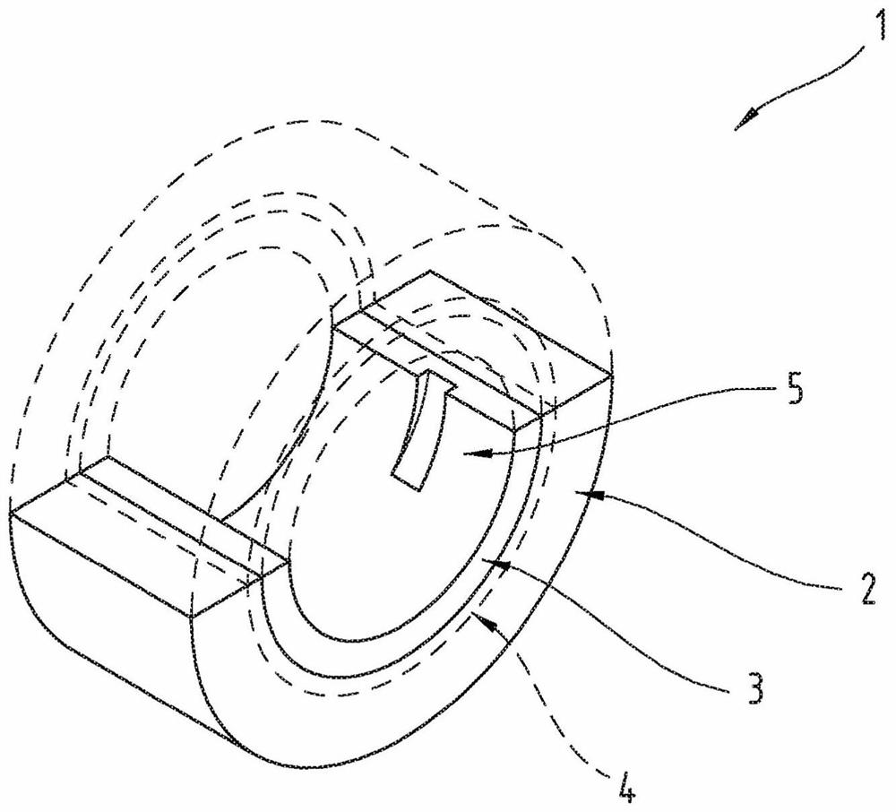
[0036] figure 1 The plain bearing element 1 is shown in oblique view. The plain bearing element 1 comprises a support layer 2 and a sliding layer 3 arranged on and connected to the support layer, or the plain bearing element consists of these two layers.

[0037] In addition to a shell design, in particular a half-shell design, the plain bearing element 1 can also b...


PUM

PropertyMeasurementUnit
depthaaaaaaaaaa

Abstract

The invention relates to a sliding bearing element (1) comprising a supporting layer (2) and a sliding layer (3), wherein at least one lubricant groove (5) is formed in the sliding layer. At least part of the lubricant groove has a surface with a surface pattern, the surface pattern having a plurality of depressions (7).

Description

technical field [0001] The invention relates to a plain bearing element comprising a support layer and a sliding layer, wherein at least one lubricant groove is formed in the sliding layer. Background technique [0002] Lubricant-induced cavitation problems are known to occur on sliding surfaces when sliding bearings are run wet. The consequence of this is a loss of efficiency and damage in particular to the sliding surfaces of the plain bearing. [0003] To deal with the cavitation problem, various solutions have been proposed in the prior art. Thus, for example WO 1999 / 045285 A1 describes a sliding bearing comprising a metal carrier, a sintered porous metal layer connected to the carrier and a lining layer penetrating into the pores of the porous metal layer and covering the sintered metal layer, the The backing layer comprises PTFE comprising 10-30% by volume of wear-resistant particulate filler, 2-10% by volume of fibrillated aramid fibers and 2-10% by volume of melt-p...

Claims


Application Information

Patent Timeline
Patent Type & Authority Applications(China)
IPC IPC(8): F16C33/10
CPCF16C33/1065F16C2240/44F16C17/022F16C33/046
Inventor J·富克斯L·黑蒂克L·哈雷艾泽J·胡摩尔D·拉纳M·伦佩尔梅尔
Owner MIBA SINTER AUSTRIA
Why Eureka
Try Eureka