Active hydraulic damper and hydraulic actuator

A hydraulic damper and hydraulic actuation technology, which is applied in the direction of liquid shock absorbers, shock absorbers, shock absorbers, etc., can solve problems such as insufficient dynamics, low limit frequency, and complexity, and achieve improved dynamic characteristics and cost advantages Convenience and improved controllability

Active Publication Date: 2009-03-25
利勃海尔运输系统股份有限公司
View PDF0 Cites 26 Cited by
  • Summary
  • Abstract
  • Description
  • Claims
  • Application Information

AI Technical Summary

Problems solved by technology

Active aerodynamic dampers are well known, but, due to their lower cut-off frequency of about 1 Hz, do not offer the possibility of high dynamics and thus optimum damping
So far, due to the complexity of technical realization, the technically mature hydraulic active damper is no longer used
In particular, earlier hydraulic actuators were insufficiently dynamic, their structure and maintenance were too complex, and their energy consumption was too high

Method used


Image

  • Active hydraulic damper and hydraulic actuator
  • Active hydraulic damper and hydraulic actuator
  • Active hydraulic damper and hydraulic actuator

Examples


Embodiment Construction

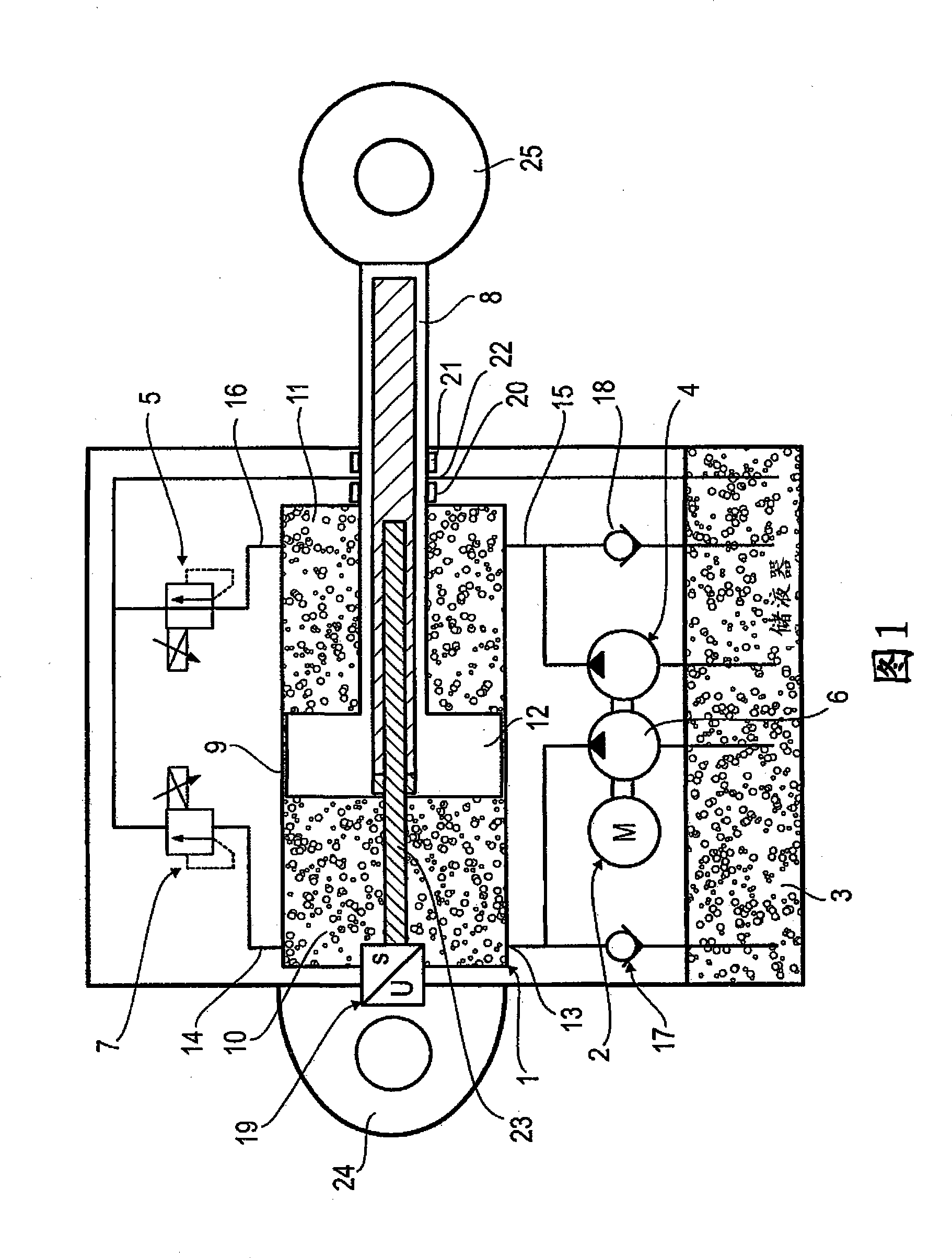
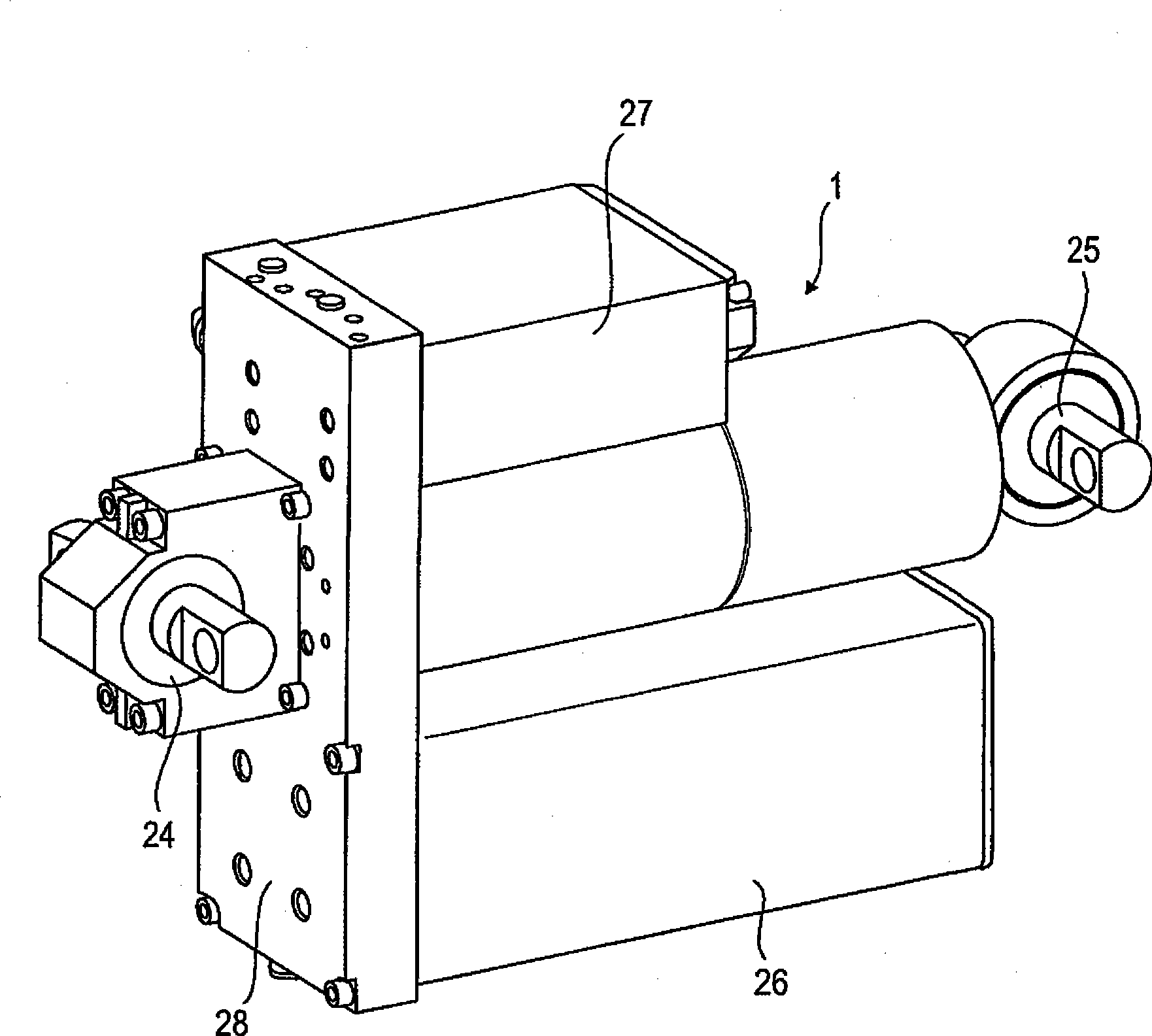
[0062] FIG. 1 shows an embodiment of the actuator of the invention in which all components of the hydraulic system are arranged at the hydraulic cylinder 1 . The hydraulic cylinder 1 is a double-acting cylinder with a cylinder space 9, a one-way piston rod 8 and a piston 12 movable in the cylinder space, which divides the cylinder space 9 into a first piston space 10 and a second piston space11. By applying a pressure difference between the first piston space 10 and the second piston space 11 , the pistons can move in opposite directions as directed by the pressure difference.

[0063] Furthermore, a position-measuring system 19 is provided, which is integrated in the hydraulic cylinder, wherein a position-measuring track 23 runs in a bore in the piston rod 8 . In this way, the movement of the piston and thus the position of the cylinder-side pivot point 24 relative to the piston-side pivot point 25 can be detected.

[0064] All components of the hydraulic system of the inve...


PUM


Abstract

The invention relates to an active hydraulic damper specially for railway vehicles, comprising a hydraulic cylinder, an electric motor, a hydraulic accumulator, at least a pump and at least a control valve. According to the invention, all components of the active hydraulic damper are arranged at the hydraulic cylinder.

Description

technical field [0001] The invention relates to a hydraulic actuator, in particular in the form of an active hydraulic damper, for rail vehicles. Background technique [0002] Semi-active dampers with varying damping forces have been widely used especially in the field of passenger cars. An active damper, ie a damper which can generate a force by itself and thus be actively moved, guarantees an improved damping effect compared to semi-active systems. Active aerodynamic dampers are known, but, due to their lower cut-off frequency of about 1 Hz, do not offer the possibility of high dynamics and thus optimum damping. So far, due to the complexity of technical realization, the technically mature hydraulic active damper is no longer used. In particular, earlier hydraulic actuators were not dynamic enough, their construction and maintenance were too complex and their energy consumption was too high. Contents of the invention [0003] It is therefore an object of the present i...

Claims


Application Information

Patent Timeline
Patent Type & Authority Applications(China)
IPC IPC(8): F16F9/19F16F9/34F16F9/32
CPCB61F5/245F16F9/3207
Inventor 安东·盖勒
Owner 利勃海尔运输系统股份有限公司
Why Eureka
Try Eureka