[0019]The present invention is designed to provide adaptable damping for the helicopter lag mode by employing a combination of controllable magnetorheological (MR) fluids (including, but not limited to those with bases of water,
silicone, hydro-carbons, and glycol) and reliable viscoelastic materials, e.g., elastomers. In addition, features of this
MagnetoRheological Fluid Elastic (MRFE) damper provide many qualities and advantages and ensure an outstanding performance as shown in this disclosure.
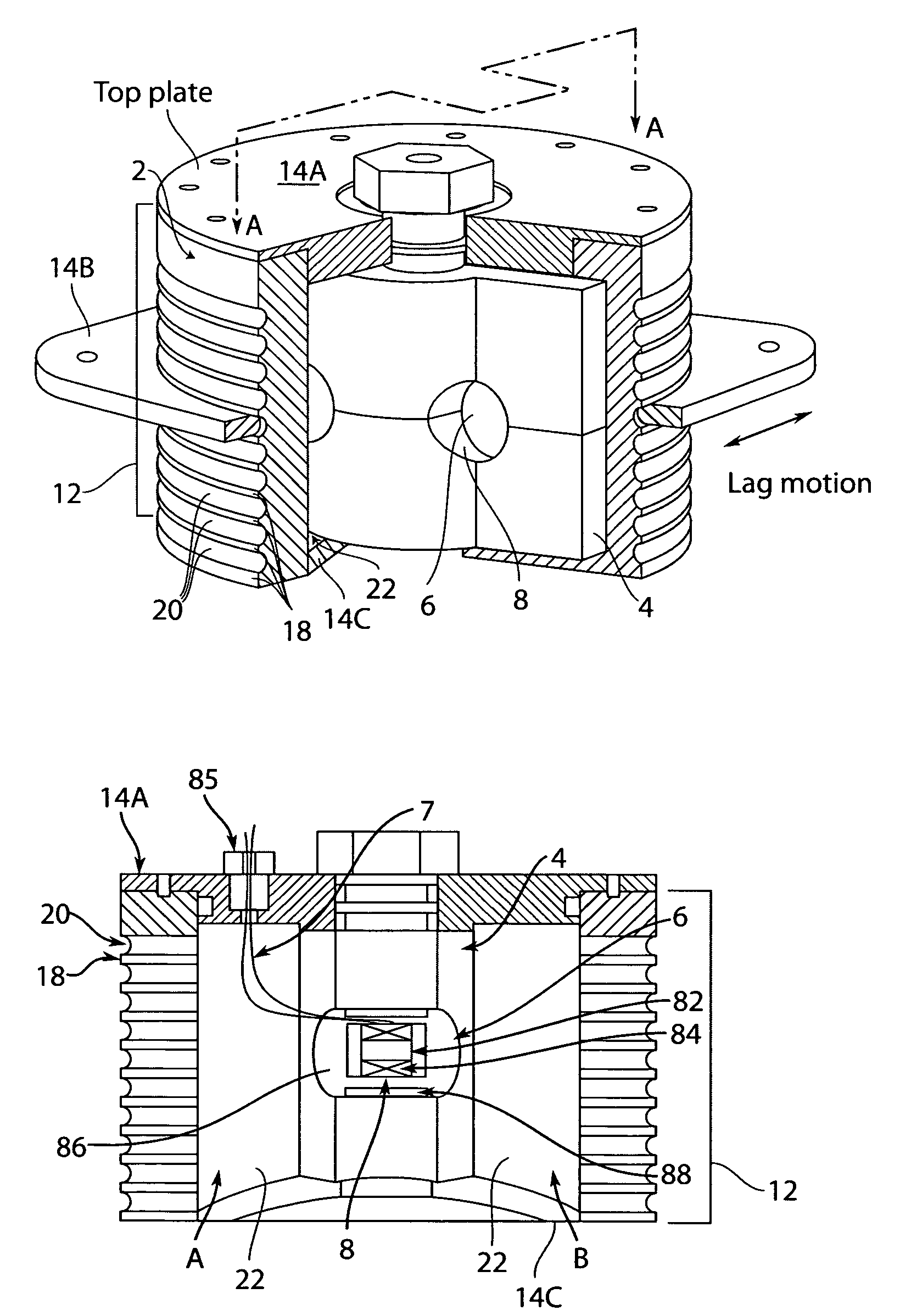
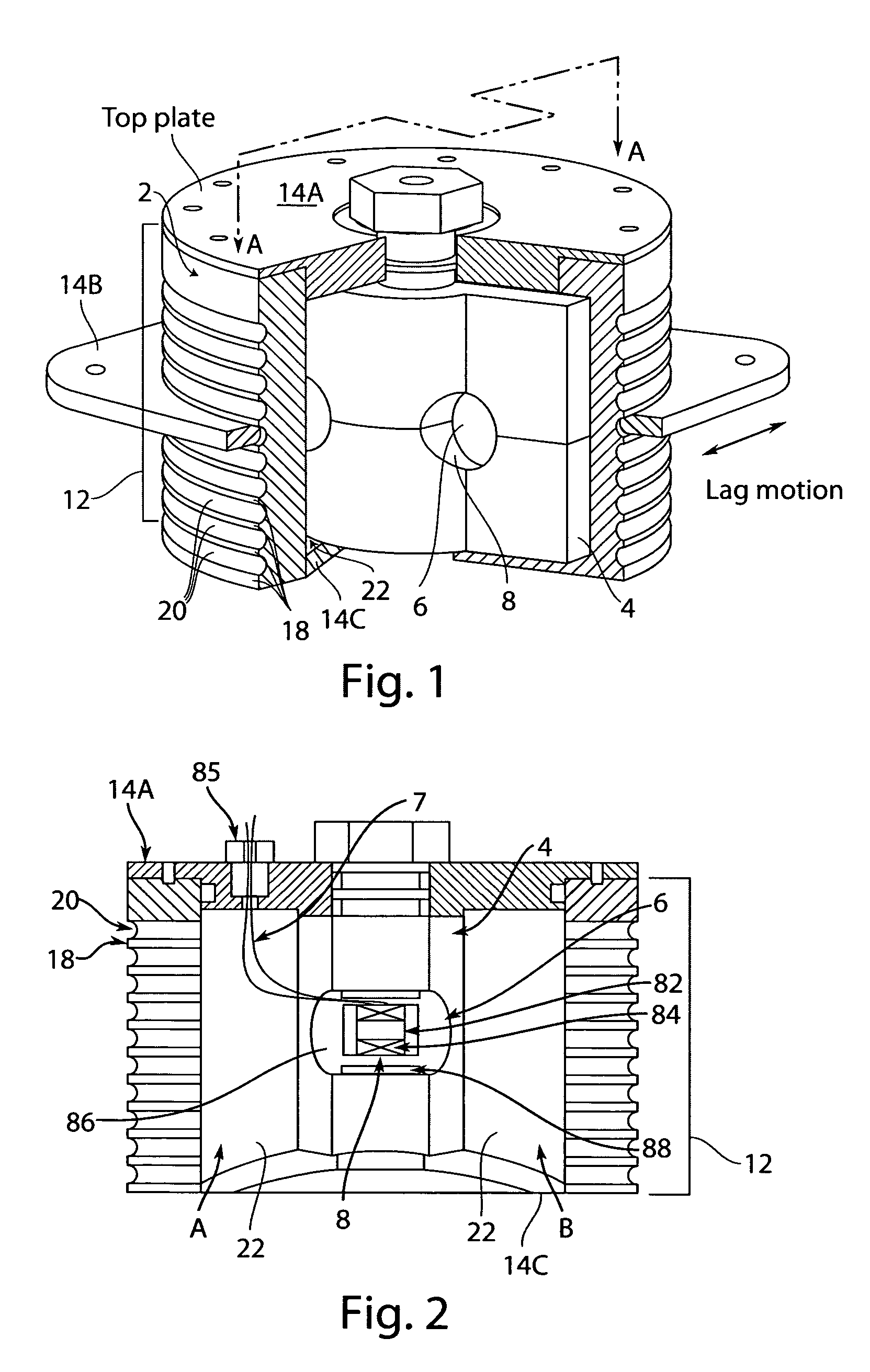
[0020]The invention provides a helicopter snubber damper, including a flexible MagnetoRheological (MR) fluid chamber and a flexible or rigid center or interior wall or damping plate, in which at least one MR flow valve is located. The snubber body can be made of metallic rings interspersed with elastomeric
layers, or a multiple lamination of metallic and elastomeric ring
layers. The cross-section of the snubber body can be in circular, elliptical, rectangular, and other symmetrical shapes. A cavity is enclosed in the snubber body, and is filled with MR fluid. A flexible or rigid center or interior wall can be placed within the cavity of the snubber body to divide the cavity into two MR fluid chambers. The shape of the center or interior wall should be compatible with the cavity in the snubber body. At least one flow port or MR valve can be located in the center or interior wall, and the MR fluid in the fluid chambers can communicate with each other though MR valves. In an alternative configuration, the
two fluid chambers communicate through an external flow channel in which the MR valve is enclosed. As the said snubber damper is installed in a
helicopter rotor system, lead-lag motion of a blade can induce shear deformation of the flexible chamber of the snubber along the out-of-surface axis of the center or interior wall. Thus, the MR fluid in one fluid chamber can be forced to flow through the MR valve into the other fluid chamber. The deformation of the flexible chamber can provide passive stiffness, and the said MR valve can provide field-controllable damping force.
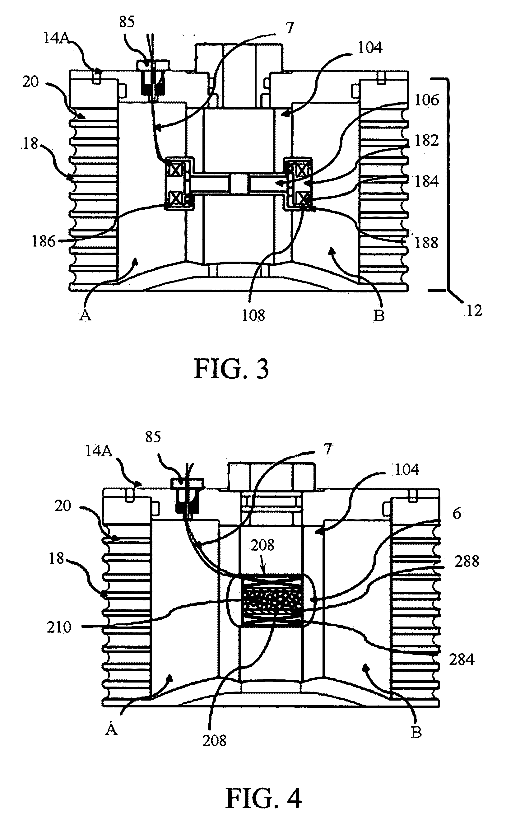
[0023]In yet another embodiment of the MR snubber damper, a snubber body can be made of plates interspersed with elastomeric
layers, or a multiple lamination of metallic and elastomeric ring layers. A rigid or semi-rigid center or interior wall can be placed within the cavity of the snubber body to divide the cavity into two MR fluid chambers. The upper edge of the center or interior wall can be fixed with the top side of the snubber body. The other
peripheral edges of the center or interior wall can be free relative to the flexible chamber, but elastomeric or rubber seal can be used to prevent fluids in the fluid chambers from communicating through the edges. As the top side of the snubber body is sheared relatively to the bottom side, the center or interior wall can move through the MR fluid reservoir in a
paddle-like motion. MR valves can, for example, be located near the lower edge of the
paddle such that the MR fluid flows through the valve with higher flow rate. The MR valve can be activated using an
electromagnet mounted at the center post of the center or interior wall. The MR valves will allow flow through the valves in the absence of field, but in the presence of
magnetic field, the MR valves will impede flow through the valves. By varying the
magnetic field, the MR damping component can be substantially modified. Meanwhile, in those snubber configurations, a pneumatic accumulator or air bladder may be incorporated into the snubber body to pressurize the flow to prevent
cavitation.
[0025]An alternate embodiment of the concentric MRFE damper comprises two concentric cylindrical tubes and a flow mode
piston-rod
assembly in structures. An outer tube is attached to the rotor head, and an inner tube connected to the blade root. An elastomeric layer is sandwiched between the said outer tube and said inner tube. The volume enclosed in the said inner tube forms a cylindrical MR fluid chamber. A flow mode
piston-rod
assembly and MR fluids are included in the said fluid chamber, and the piston divides the said inner cylinder into a first chamber positioned on the rod side of the piston
assembly and a second chamber positioned on the opposite side of the piston. The MR fluid in the first chamber communicates with the MR fluid in the second chamber through a field-activated valve in the said piston. The said flow valve is configured to be influenced by the magnetic field, which is provided by an
electromagnet enclosed in the piston such that the said MR fluid flowing through the said flow valve can be regulated. To allow for volumetric compensation as the said rod slides in and out of the cylinder and to prevent fluid
cavitation, a pneumatic chamber is located at one end of the said second fluid chamber. The said pneumatic chamber allows for volumetric compensation as the said rod slides in and out of the cylinder. The said rod and piston assembly is fixed relative to the said outer tube. An elastomeric rod seal is sandwiched between the said inner tube and said rod in a configuration so that a conventional sliding rod seal is eliminated. Thus, the lead-lag motion of the blade induces a relative translation between the said inner tube and the said outer tube, which in turn leads to a shear deformation of the said
elastomer along the said cylindrical chamber body length. The deformation of the said
elastomer provides passive stiffness and damping for the lead-lag mode of the rotor blade. Meanwhile, the lead-lag motion induces a relative translation between the said piston-rod assembly and the said inner tube, and forces the MR fluid to flow through the said valve so that field-dependent damping force is added to the output force of the damper. In addition, the lead-lag motion leads to a shear deformation of the said elastomeric seal, and the deformation of the said seal provides additional stiffness and damping. This embodiment of the invention also provides a space to accommodate a counter
centrifugal force device such as an
electromagnetic coil to provide longitudinal magnetic force to mitigate effect of
sedimentation of the iron particles due to a
centrifugal force field.

