
Delivery system for magnetorheological fluid

a technology of magnetorheological fluid and delivery system, which is applied in the direction of valve operating means/release devices, manufacturing tools, lapping machines, etc., can solve the problems of presenting several problems, unable to meet the requirements of the application, and the suspension of mr fluid is relatively unstabl

Inactive Publication Date: 2005-10-18
QED TECH INT
View PDF6 Cites 45 Cited by
  • Summary
  • Abstract
  • Description
  • Claims
  • Application Information

AI Technical Summary

Benefits of technology

[0022]FIG. 7 is an isometric view, partially in cutaway, of...

Problems solved by technology

MR fluid is a relatively unstable suspension because the magnetic particles tend readily to agglomerate and to settle out of suspension and thereby stagnate.
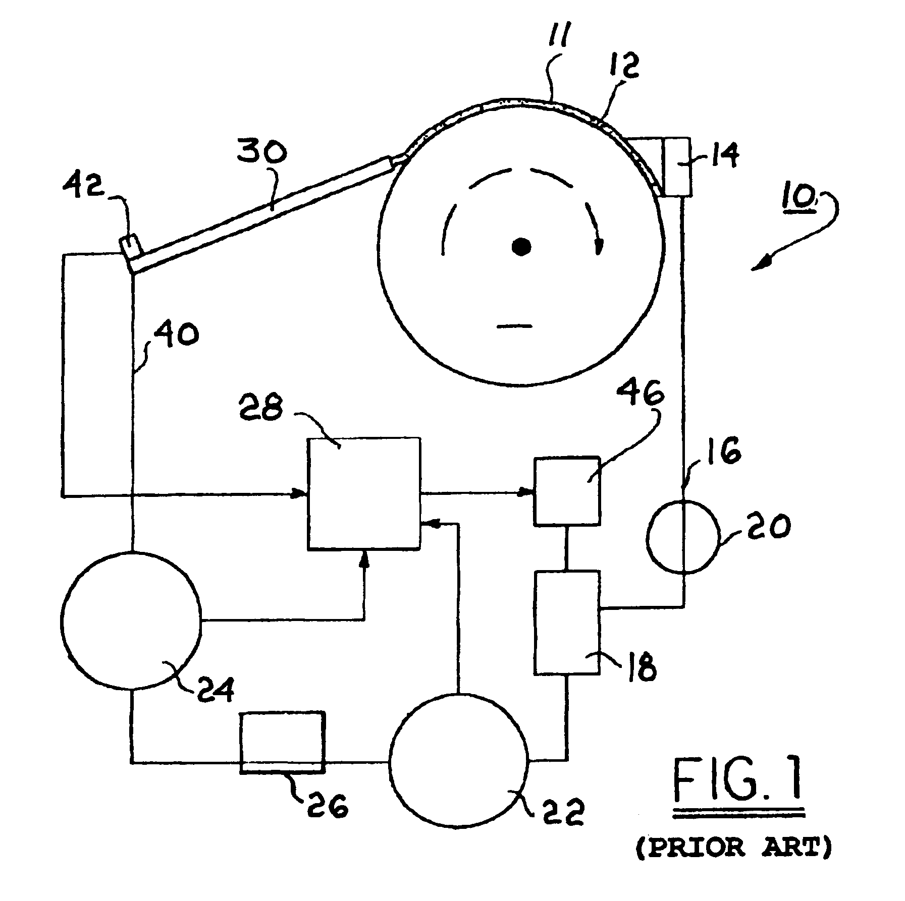
Because of these various requirements, the prior art FDS is relatively complex and includes a first peristaltic pump for removing spent fluid from a scraper at the work zone and returning the fluid to a reservoir; a mixer in the reservoir for rehomogenizing the fluid; a tempering subsystem at the reservoir for cooling the fluid, which tends to become heated in the work zone; a second peristaltic pump and cylindrical nozzle having a fixed restriction for redispensing the fluid; a pulse-dampener for removing pulses generated by the pumps; and a viscosity measuring and correcting subsystem.
Several problems are presented by the prior art FDS.
First, the system is cumbersome, as it is essentially an assemblage of discrete components, each intended to perform a single task.
Thus, the system is wasteful of space.
Second, the flow control system requires a positive-displacement (PD) pump.
Some known PD pumps such as gear pumps are unsuited to the task of pumping MR fluids.
A peristaltic pump can meet the positive-displacement need over a short period of time; however, the pulsating output mandates the pulse-dampening apparatus already noted, and the delivery lines within the pump are subject to fatigue and must be replaced frequently.
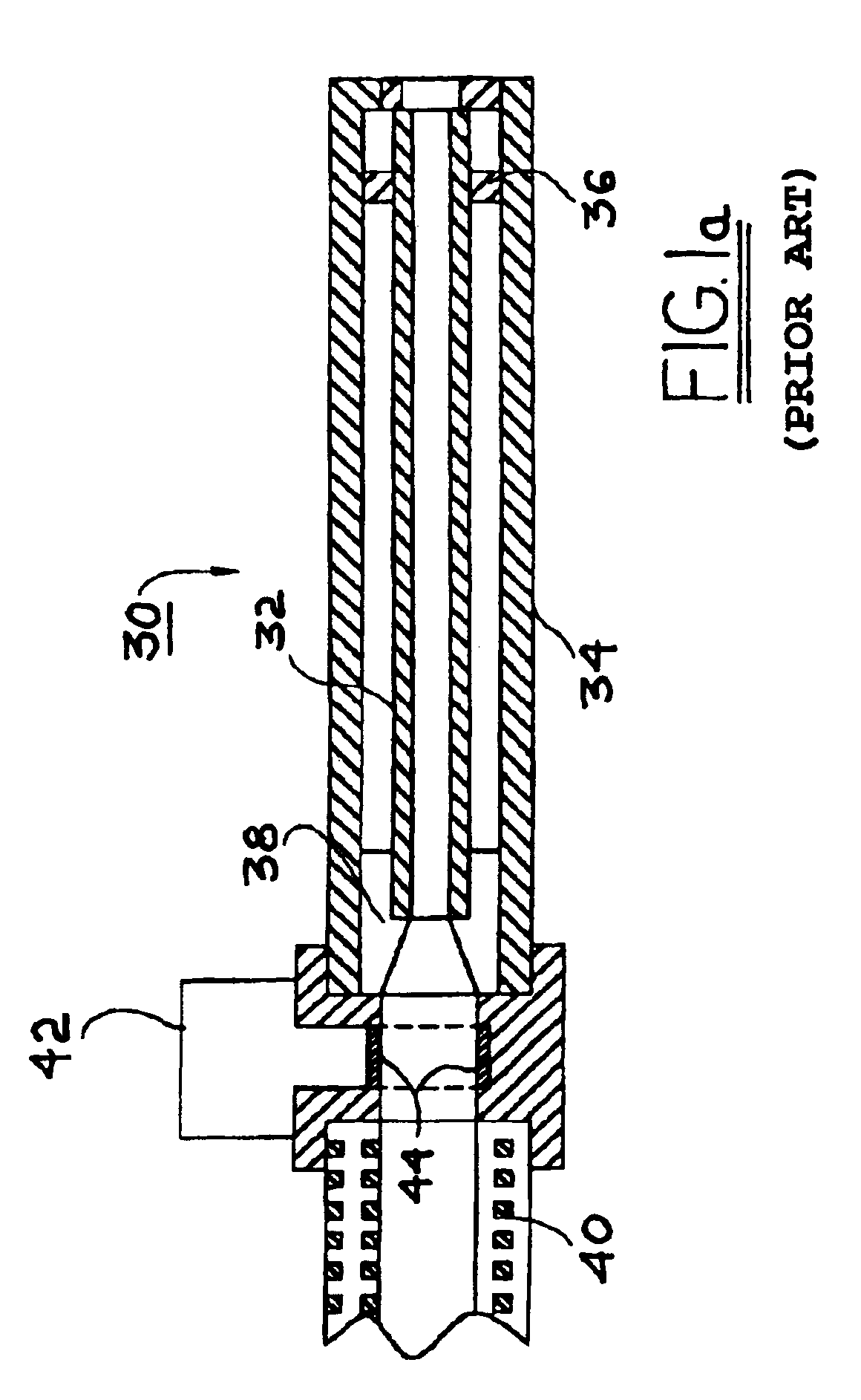
Third, correct composition of the MR fluid being redispensed is inferred from an inline viscometer which incorporates a cylindrical nozzle that, for flow reasons, must be relatively long and thus is cumbersome.

Method used


Image

  • Delivery system for magnetorheological fluid
  • Delivery system for magnetorheological fluid
  • Delivery system for magnetorheological fluid

Examples


Embodiment Construction

[0023]The benefits and advantages of a magnetorheological fluid delivery system in accordance with the invention may be better appreciated by first considering a prior art system.

[0024]Referring to FIG. 1, a prior art fluid delivery system 10 (FDS) is shown for providing MR fluid 11 to a carrier surface 12 of a magnetorheological finishing apparatus (not otherwise shown) at a constant aim flow rate and viscosity; for recovering MR fluid from the carrier surface; and for conditioning recovered MR fluid for re-use. MR fluid 11 is scraped from the carrier surface 12 by scraper 14 and returned via line 16 to an inline mixing and tempering vessel 18 wherein agglomerates are broken up, carrier fluid is replenished as described below, and the reconstituted MR fluid is re-tempered to an aim temperature. A prior art system typically includes a supplementary peristaltic pump 20 to acquire the spent MR fluid from scraper 14 and deliver it to vessel 18. Retempered MR fluid is withdrawn from ves...


PUM

PropertyMeasurementUnit
Magnetic fieldaaaaaaaaaa

Abstract

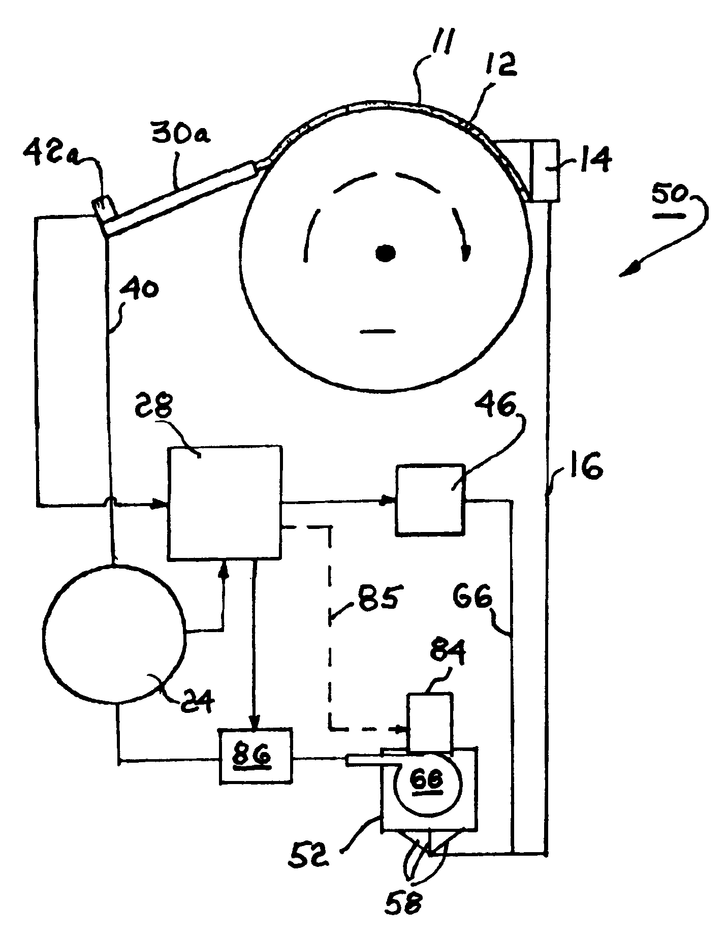
A magnetorheological fluid delivery system includes a mixing and tempering vessel. Fluid is admitted to the vessel via a plurality of tangential ports, creating a mixing of the fluid in the vessel and promoting homogeneity. Fluid may be reconstituted in the vessel by metered addition of carrier fluid. A fixed-speed centrifugal pump disposed in the vessel pressurizes the system. Fluid is pumped through a magnetic-induction flowmeter and a magnetic flow control valve having solenoid windings whereby MR fluid is magnetically stiffened to restrict flow. A closed-loop feedback control system connects the output of the flowmeter to performance of the valve. A nozzle having a slot-shaped bore dispenses MR fluid for re-use in the work zone. A planar-diaphragm flush-mounted pressure transducer at the entrance to the nozzle and flowmeter inferentially measure relaxed viscosity and provide signals to a computer for dispensing metered amounts of carrier fluid into the mixing vessel to assure correct composition of the reconstituted fluid as it is dispensed.

Description

BACKGROUND OF THE INVENTION[0001]1. Field of the Invention[0002]The present invention relates to methods and apparatus for circulating and dispensing fluids; more particularly, to methods and apparatus for circulating and dispensing fluids having magnetorheological properties; and most particularly, to methods and apparatus for managing and metering magnetorheological fluids being used in a magnetorheological finishing apparatus.[0003]2. Discussion of the Related Art[0004]It is well known in the art of finishing and polishing surfaces to use, as a finishing agent, particulate fluid suspensions having magnetorheological properties. Such fluids, known as magnetorheological fluids (MR fluids), comprise magnetically soft particles which can become oriented and magnetically linked into fibrils in the presence of a superimposed magnetic field, thereby increasing the apparent viscosity of the fluid by many orders of magnitude. Such increase is known as magnetic “stiffening” of the MR fluid...

Claims


Application Information

Patent Timeline
IPC IPC(8): B24B31/00B24B31/112B24B57/04B24B57/00F16K31/06F16K13/00F16K13/10B24B57/02B24B37/00
CPCB24B1/005B24B31/112B24B57/04F16K13/10F16K31/06Y10S137/909Y02P70/10
Inventor KORDONSKI, WILLIAMHOGAN, STEPHENCARAPELLA, JERRY
Owner QED TECH INT
Learn More