System and method for self-powered magnetorheological-fluid damping

a technology of magnetorheological fluid and damping system, which is applied in the field of magnetorheological fluid damping, can solve problems such as damping mechanical vibrations

Inactive Publication Date: 2008-03-06
WERELEY NORMAN +1
View PDF17 Cites 47 Cited by
  • Summary
  • Abstract
  • Description
  • Claims
  • Application Information

AI Technical Summary

Problems solved by technology

Furthermore, the step of dampening the mechanical vibrations may include dampening a resonance frequency of an engine.

Method used


Image

  • System and method for self-powered magnetorheological-fluid damping
  • System and method for self-powered magnetorheological-fluid damping
  • System and method for self-powered magnetorheological-fluid damping

Examples


Embodiment Construction

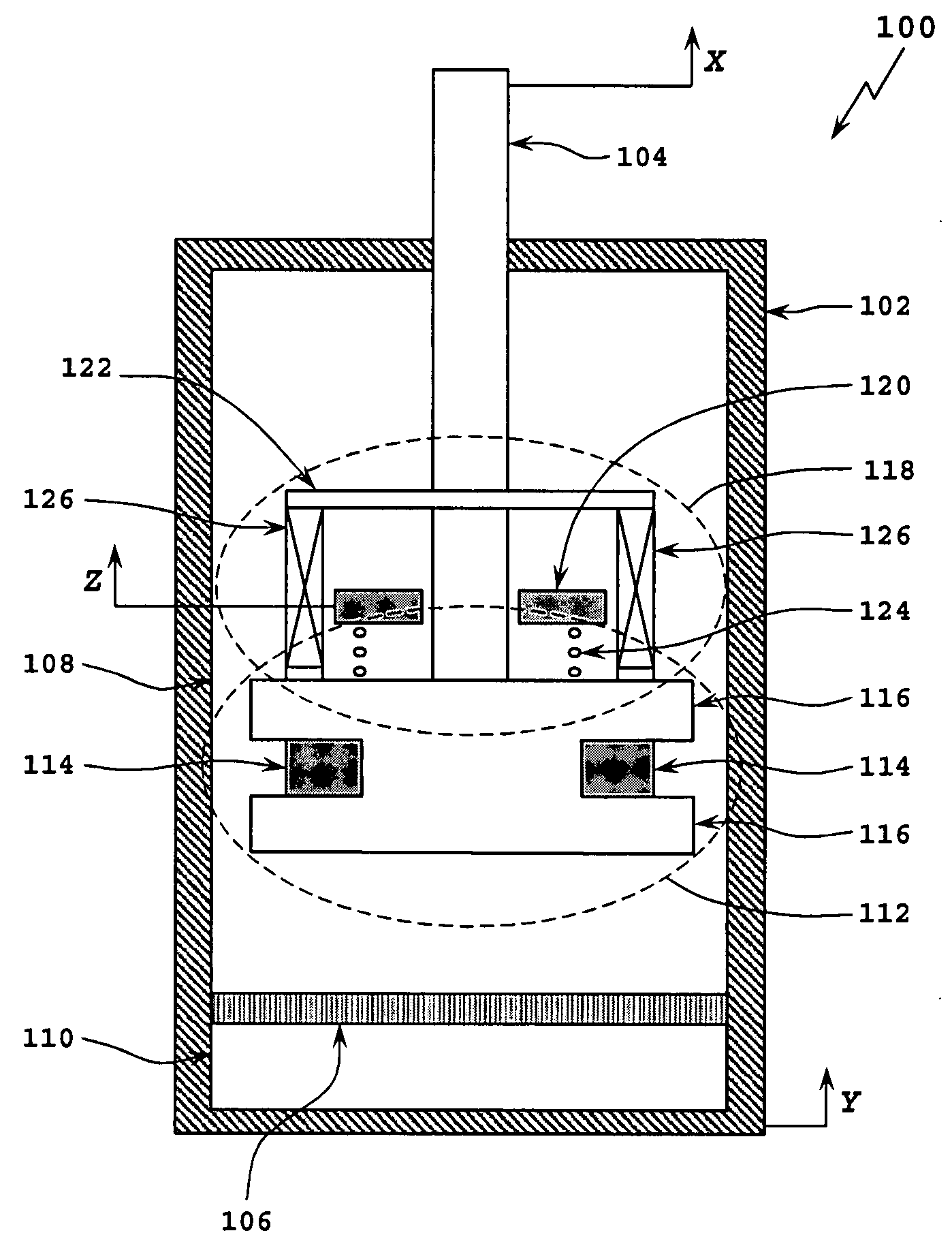
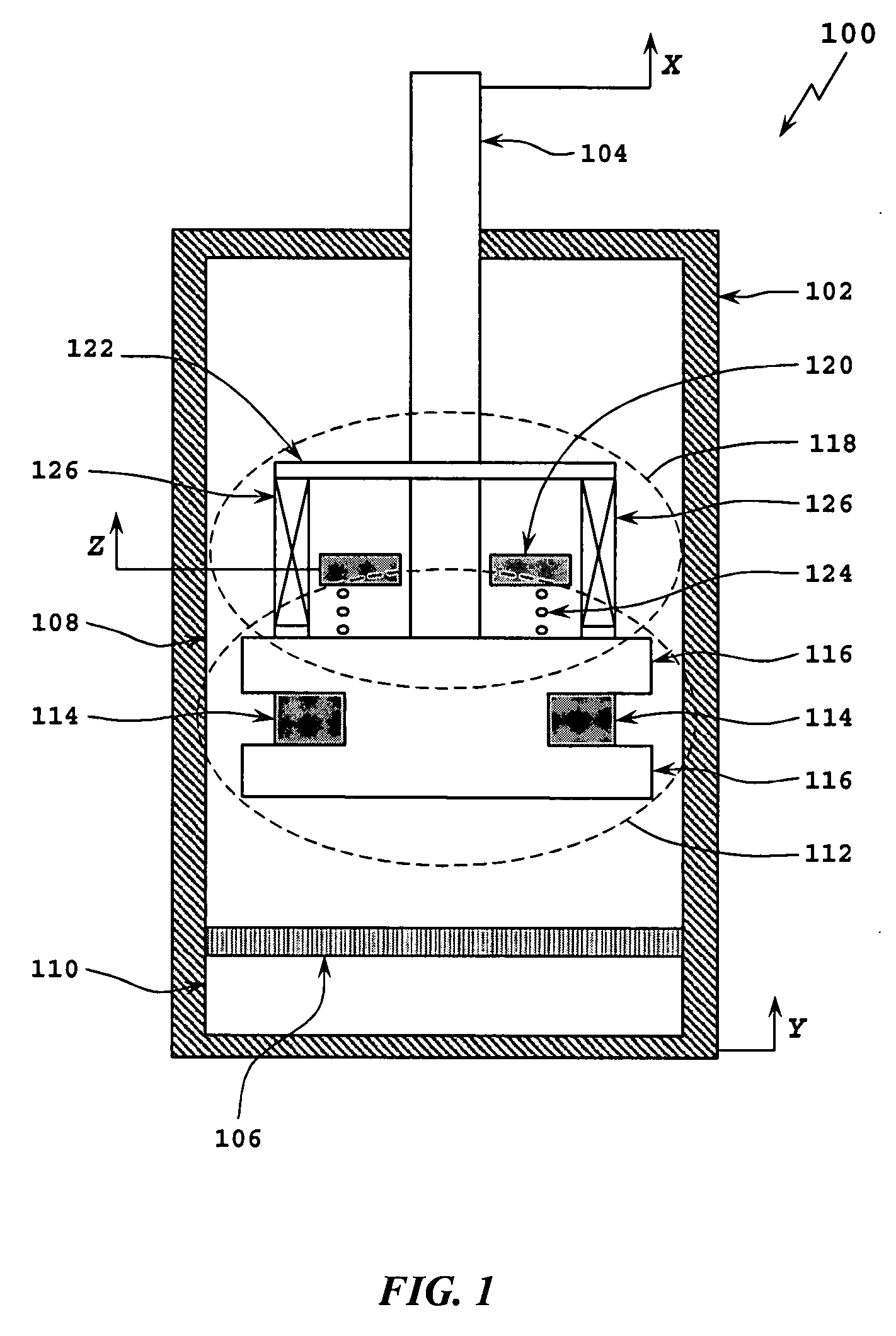
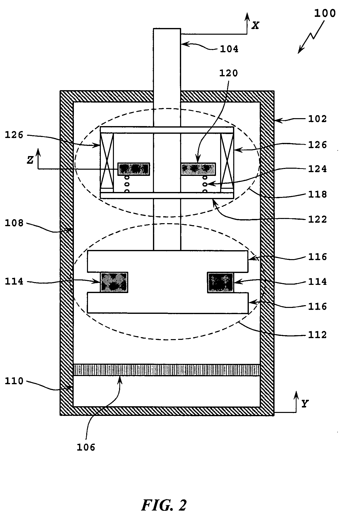
[0020]Referring to the drawings, simultaneously refer to FIGS. 1, 2, and 3 which depict a schematic diagram of an MR fluid damping system 100. MR fluid damping system 100 may be used to dampen engines, used in an engine mount, protect equipment, and / or may be used to dampen any other device from mechanical vibrations. For example, MR fluid damping system 100 may be used in a car to dampen the engine from the frame. Additionally or alternatively, MR fluid damping system 100 may be used in automobile “shocks” to dampen the mechanical vibrations coming from the tires to the passengers.

[0021]MR fluid damping system 100 may include a hydraulic cylinder 102 that houses fluid, e.g., MR fluid, air, oil, and / or other material, liquids or components. MR fluid system 100 may also include piston rod 104 in sliding in sliding engagement with hydraulic cylinder 102. The term “sliding engagement” is not intended to engagements in which the two items are touching, e.g., piston rod 104 may utilize o...


PUM


Abstract

A system and method for self-powered magnetorheological-fluid damping of mechanical vibrations includes a hydraulic cylinder. The hydraulic cylinder is configured for at least partially disposing magnetorheological fluid therein. A piston head is disposed within the hydraulic cylinder. The piston head has first and second sides and is configured to be in sliding engagement with the hydraulic cylinder. A piston rod is at least partially disposed within the hydraulic cylinder and is connected to the piston head on the first side. The system also includes a vibration absorber assembly having housing. The vibration absorber assembly is configured to transduce mechanical vibrations of the piston rod to electric current.

Description

PRIORITY CLAIM TO PROVISIONAL APPLICATION[0001]This patent application claims priority to and the benefit of U.S. Provisional Patent Application No. 60 / 824,141, filed in the U.S. Patent and Trademark Office on Aug. 31, 2006, entitled “Self-Powered Magnetorheological Dampers”.BACKGROUND[0002]1. Technical Field[0003]The present disclosure relates to magnetorheological-fluid damping, and, in particular, to a system and method for self-powered magnetorheological-fluid damping of mechanical vibrations.[0004]2. Description of Related Art[0005]Generally, magnetorheological fluids (herein referred to as “MR” fluids) are a class of fluids that change in viscosity in the present of a magnetic field. An MR fluid may have the viscosity of commercially available motor oil when no magnetic field is present and may behave similarly to a solid when a magnetic field is applied (e.g., it may become a viscoelastic solid). Therefore, they exhibit controllable yield strength. When no magnetic field is p...

Claims


Application Information

Patent Timeline
Patent Type & Authority Applications(United States)
IPC IPC(8): F16F9/53F17D3/00
CPCF16F9/535F16F7/1011Y10T137/034
Inventor WERELEY, NORMANCHOI, YOUNG-TAI
Owner WERELEY NORMAN
Why Eureka
Try Eureka