
Fluid haptic interface with improved haptic rendering using a torque or load sensor

a haptic rendering and torque technology, applied in the direction of limiting/preventing/returning movement of parts, controlling members, alarms, etc., can solve the problems of affecting the perceived haptic quality, affecting the haptic rendering, and applying a significant load

Active Publication Date: 2018-02-20
COMMISSARIAT A LENERGIE ATOMIQUE ET AUX ENERGIES ALTERNATIVES
View PDF11 Cites 48 Cited by
  • Summary
  • Abstract
  • Description
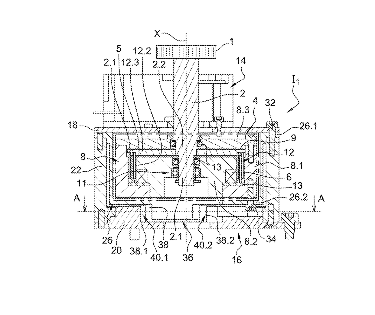
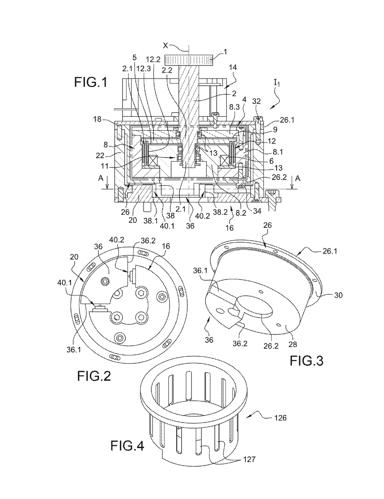
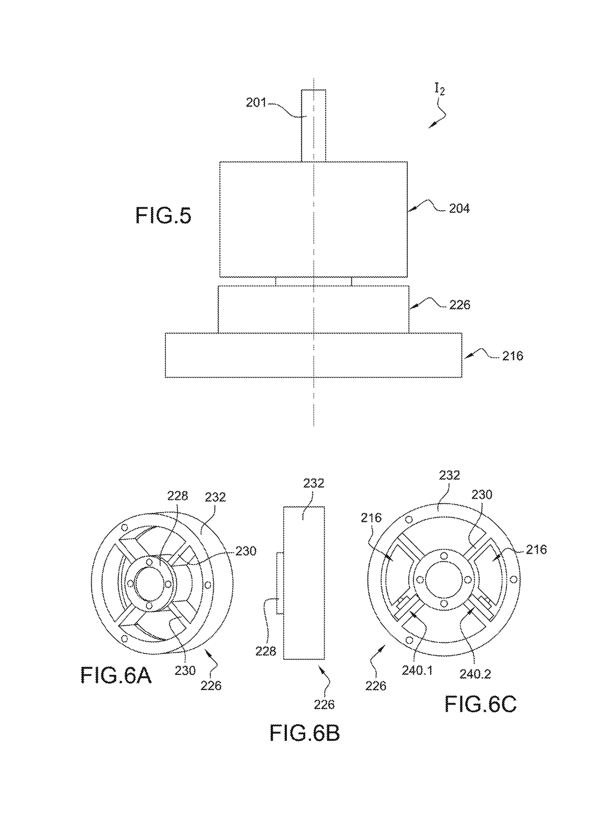
  • Claims
  • Application Information

AI Technical Summary

Benefits of technology

The present invention offers a haptic interface with improved haptic rendering, particularly in the case of reversed movement. It reduces delay in controlling the interface by anticipating the user's movement action. Additionally, it reduces electricity consumption and magnetic field application by determining the user's intention by processing current position sensor data and motion sensors. The interface can also modulate the haptic sensation based on the actuation speed of the element for interacting with the user, improving control over the haptic sensation. Load sensors or strain sensors are optimally positioned to maximize the measurement sensitivity of the torque or force.

Problems solved by technology

In this configuration where the haptic sensation is an angular function of the position of the button, the production of certain haptic patterns is tainted with undesirable effects which impair the perceived haptic quality.
However, the choice of the spring stiffness is complex; indeed, if the spring is too stiff, the user must apply a significant load to oppose the stiffness of the spring until a resulting movement detectable by the angular position is generated.
Conversely, if the spring stiffness is too low, the user will perceive the stiffness thereof instead of perceiving a stop (theoretically infinite stiffness), the stop sensation produced is then not of good quality.
More generally, the simulation of a sensation when the haptic pattern in one direction is different to the haptic pattern in the opposite direction can generate this sticking sensation which impedes the satisfactory haptic rendering of the interface.
Reproducing a haptic pattern, for example a stop, also involves the drawback of requiring continuous electricity consumption, due to the power supply of the coil to create the magnetic field modifying the apparent viscosity in order to generate the haptic pattern sought, even if the user has released the button, since the fact that the user has released the button is not detected.

Method used


Image

  • Fluid haptic interface with improved haptic rendering using a torque or load sensor
  • Fluid haptic interface with improved haptic rendering using a torque or load sensor
  • Fluid haptic interface with improved haptic rendering using a torque or load sensor

Examples


Embodiment Construction

[0008]Consequently, one aim of the present invention is that of offering a haptic interface offering improved haptic rendering, particularly in the case where the haptic pattern varies between a first movement direction and a second direction opposite the first movement direction, for example in the case of reproducing a stop.

[0009]The aim described above is achieved by a haptic interface comprising a member for interacting with the user and a member for interacting with a fluid, the viscosity whereof varies according to a control stimulus, the two members being secured at least in rotation or at least in translation, means for generating a variable stimulus, a sensor for measuring the current position of the element for interacting with the user, and means for detecting the user's intended action before the motion applied to the element for interacting with the user becomes perceptible for the user and for the position measurement sensor in order to determine the direction of movem...


PUM


Abstract

A haptic interface, including: a button which can be rotated by a user; an interaction element interacting with a magnetorheological fluid, secured to the button; a mechanism measuring a current position of the button; a brake including a magnetorheological fluid and a generation system to generate a magnetic field in the fluid; a controller configured to generate orders for the system to generate a magnetic fluid to modify a value of the magnetic field; and a mechanism to detect torque exerted by a user on the button to know direction of the torque and whether the torque is greater than a given value for a given direction, the controller controlling generation of a magnetic field based on obtained information about the torque at least when the button indicates zero or low speed.

Description

FIELD OF THE INVENTION AND STATE OF THE RELATED ART[0001]The present invention relates to a haptic interface with improved haptic rendering.[0002]A haptic interface can take the form of a rotary button operated by a user, in this case, the interface opposes a torque resisting the user according to the angular position of the actuation button and the movement applied by the user, thus making it possible to define haptic patterns which will be perceived by the user when turning the button.[0003]The resistant torque can be transmitted to the button via a magnetorheological fluid, the apparent viscosity whereof is modified by applying a magnetic field in order to define the predefined haptic patterns. In this configuration where the haptic sensation is an angular function of the position of the button, the production of certain haptic patterns is tainted with undesirable effects which impair the perceived haptic quality.[0004]For example in the case where the interface is to reproduce a...

Claims


Application Information

Patent Timeline
Patent Type & Authority Patents(United States)
IPC IPC(8): G08B21/00G05G5/03G05G1/08F16F9/53G05G1/02G08B6/00
CPCG05G5/03F16F9/535G05G1/08G05G1/02G08B6/00G05G2505/00G06F3/016G06F3/0362H01H19/00H01H2003/008
Inventor HAFEZ, MOUSTAPHALOZADA, JOSEECK, LAURENTCHANGEON, GWENAEL
Owner COMMISSARIAT A LENERGIE ATOMIQUE ET AUX ENERGIES ALTERNATIVES
Learn More