A
gate valve is generally known to those in the art as being poor for controlling flow other than in a fully-opened or fully-closed position.
The interface between the gate and its seat generally erodes and is prone to maintenance.
As can be seen, the flow path is somewhat circuitous resulting in generally higher friction losses, nonlaminar flow, and may prematurely induce flow separation and / or
cavitation.
Thus, flow rates tend to be less than those of a fully-opened gate valve, the fluid flow path tends to wear, and the
globe valve, because of its inherent construction, tends to be bulky.
The
ball valve tends to be somewhat bulky, generally uses two seating surfaces on either side of the ball, and may be somewhat expensive to manufacture.
While the
valve stem may be remotely actuated by motors and other devices known to those in the art, it may not be suitable for sealed installations where it might be desirable to completely encase the valve, remote
actuator, and seat in a conduit for efficient installation nor is it suitable for installing in a wall structure where access to the
actuator is restricted because of the
transverse orientation.
Those in the art typically concentrated on a
globe valve type seat because of the inherent difficulty of actuating a gate valve from within the conduit.
However, it causes other problems.
The wear surfaces may be prone to
water erosion and deposits from water impurities.
Once the
nose was crushed or deformed, it required even harder tightening of the
nose which eventually lead to leaking (the famous "drip drip").
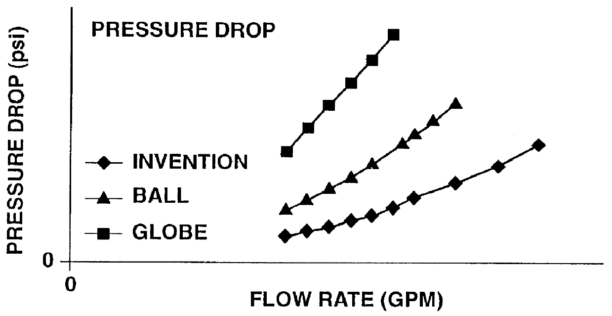
Also, the inherent design of the
nose portion, engaging an aperture, causes a significant pressure drop, as those with ordinary skill in the art would immediately recognize.
This significant pressure drop reduces flow rates.
Therefore, increased wear and increased maintenance resulted from not only the rotational movement, but the longitudinal movement as it engaged those portions of the
valve seat.
While an increase in size of the typical valve might achieve the necessary flow rates, typically, this was not a viable option because of size, costs, and compatibility with other components of the
piping system.
Thus, prior attempts to remotely seal the
water flow or other liquids lead to
high pressure drops, low flow rates, and maintenance.
Thus, an installation was not able to use the typical valving of a typical freeze resistant hydrant--instead, it required a direct connection to other
piping with sophisticated valving controls.
The sophisticated valving, as those with knowledge of sprinkler systems would recognize, required expensive controls, maintenance, purging during off-season uses, local and national codes, and other issues.
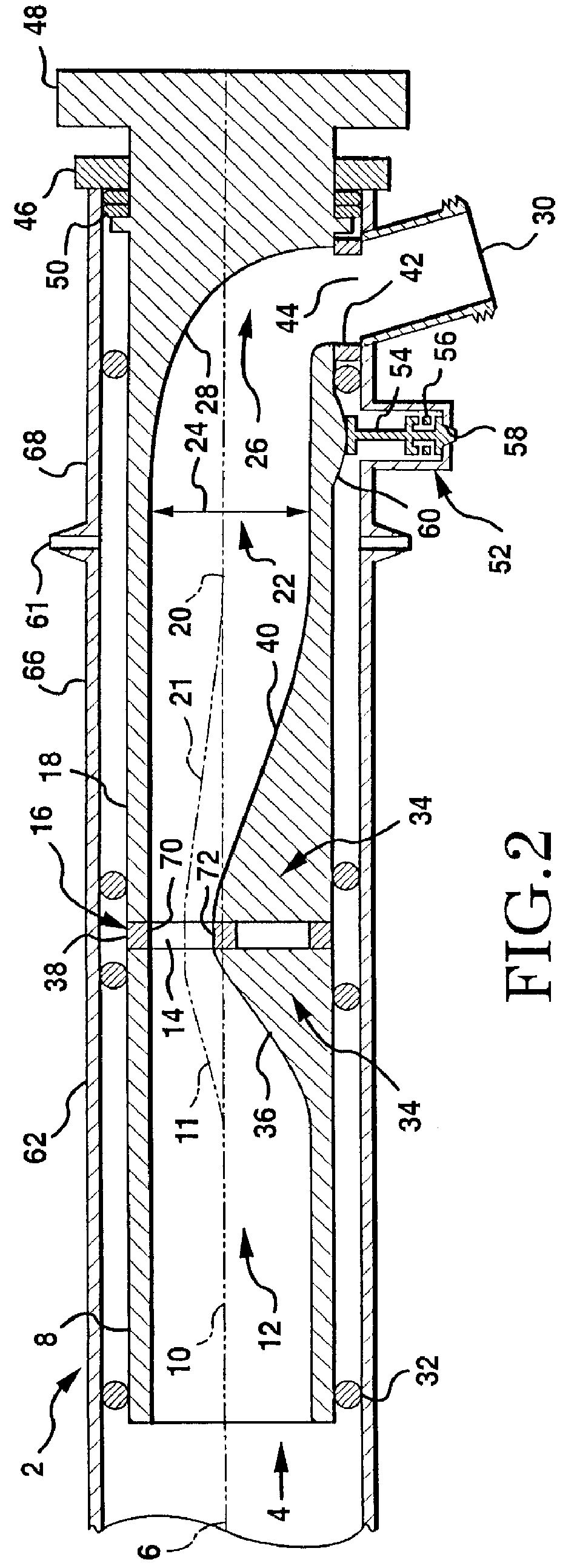
However, the additional turbulence and volume contained by the
valve stem in the flow path results in additional loss of efficiency, increased resistance and friction, and lower flow rates.
This has resulted in the above-discussed problems, such as poor flow rates.

