Claw pole generator and closure body for a claw pole generator

a technology of claw pole generator and closure body, which is applied in the direction of dynamo-electric machines, magnetic circuit rotating parts, magnetic circuit shape/form/construction, etc., can solve the problems of annoying interference noises in the rotor and stator

Inactive Publication Date: 2010-11-16
SEG AUTOMOTIVE GERMANY GMBH
View PDF18 Cites 2 Cited by
  • Summary
  • Abstract
  • Description
  • Claims
  • Application Information

AI Technical Summary

Benefits of technology

[0005]In a favorable feature, the closure body, between axially adjacent pockets, has a respective covering rib extending obliquely to a rotary axis; the covering rib covers the adjacent magnet poles on the outside on their lateral edges. As a result of this, it is possible for the magnet poles to be fixed securely in the pockets by form-locking engagement. A magnet pole can be thrust with its tips between the two lateral covering ribs and the pocket wall located behind the magnet pole.
[0006]In a further favorable feature, the pockets only partially cover the magnet poles on the inside. Preferably, only the tips of the magnet poles are inserted into the pockets. Thus the mass and moment of inertia of the rotor of the assembled closure body can advantageously be kept low.
[0007]If the closure body has an opening between respective adjacent covering ribs and the opening keeps a pole root of the respective magnet pole, extending between the adjacent covering ribs, free on the inside, considerable economies of weight can be achieved. As a result, cooling of the rotor can be improved. In manufacture, it also proves advantageous that the inflow of impregnating agent, such as impregnating resin, for fixing a typical exciter coil and for closing small gaps between the closure body and the magnet poles is simplified. This improves the noise deadening of the closure bodies still further. In a favorable feature, air gaps between the magnet poles and the closure body are therefore filled with a solid material, preferably impregnating resin. The closure body is preferably made from a nonmagnetic material, preferably aluminum, an aluminum alloy, a magnesium alloy, or plastic. No expensive permanent-magnetic materials are necessary.
[0008]In a favorable feature, a ratio of the inside radius of the closure body to the outside radius of the pole wheel half is at most 0.98. Preferably, the ratio is in the range between 0.95 and 0.85, and in particular between 0.94 and 0.87. This produces especially favorable noise deadening.
[0009]In a favorable feature, in the axial direction an overshoot is embodied above the pockets that is at least 10% longer than a stator iron, preferably at least 20% and especially preferably approximately 30% longer. As a result, the influence of noise interference that arises from the winding head and not only from the stator iron is reduced. The noise deadening is further improved.
[0010]The cooling can advantageously be ensured if at most 60% and especially preferably at most 50% of a projection area between the pole roots is covered by a fan.
[0011]Moreover, a closure body for closing gaps between adjacent magnet poles of two pole wheel halves of a claw pole generator is proposed which is embodied as a zigzag-like ring in which there is a pocket in the tip of each zigzag.

Problems solved by technology

In claw pole generators, it is known that annoying interference noises can arise in the rotor and stator if the air volumes between the clawlike magnet poles are excited to vibration as a consequence of protrusions and indentations on the stator and winding head geometry.

Method used


Image

  • Claw pole generator and closure body for a claw pole generator
  • Claw pole generator and closure body for a claw pole generator
  • Claw pole generator and closure body for a claw pole generator

Examples


Embodiment Construction

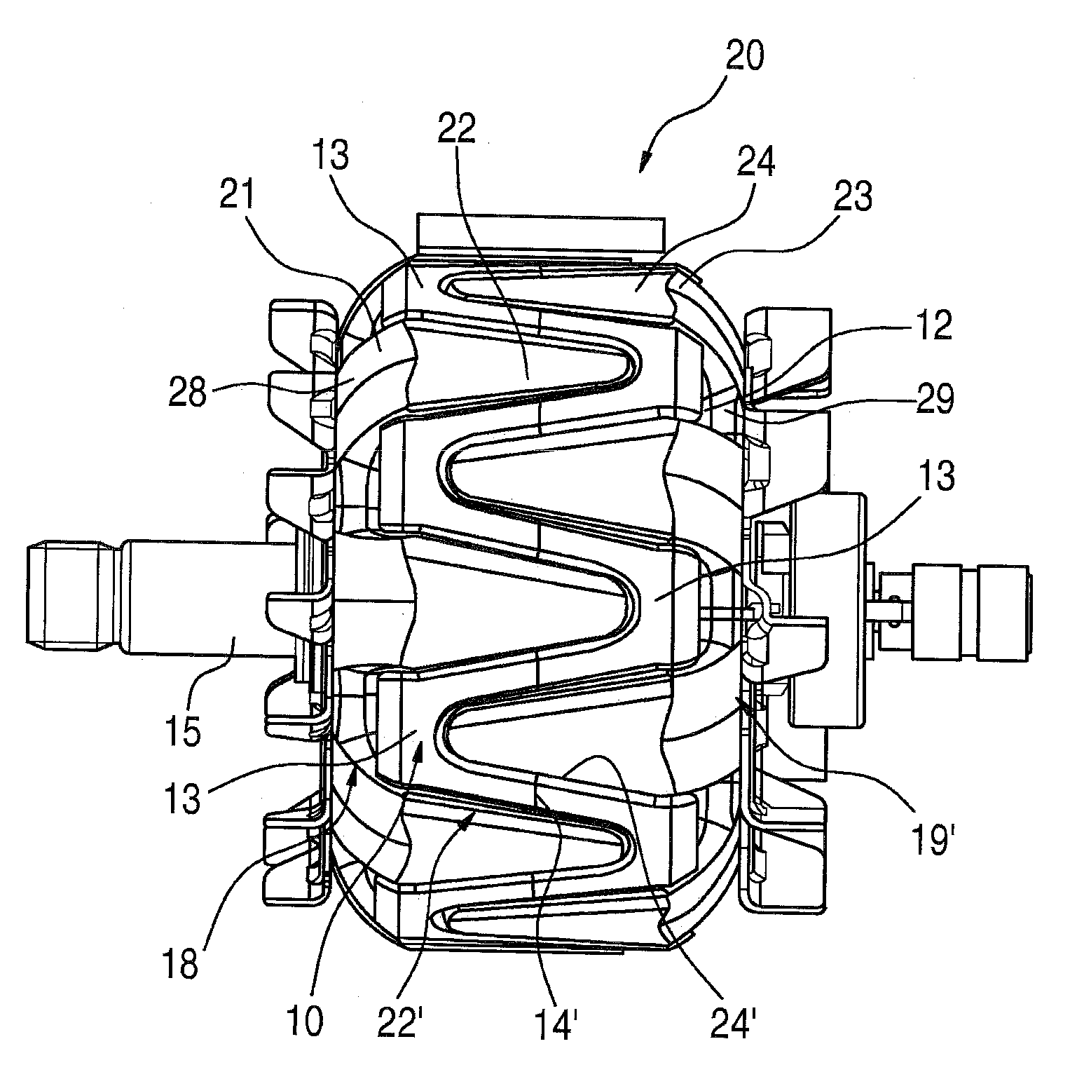
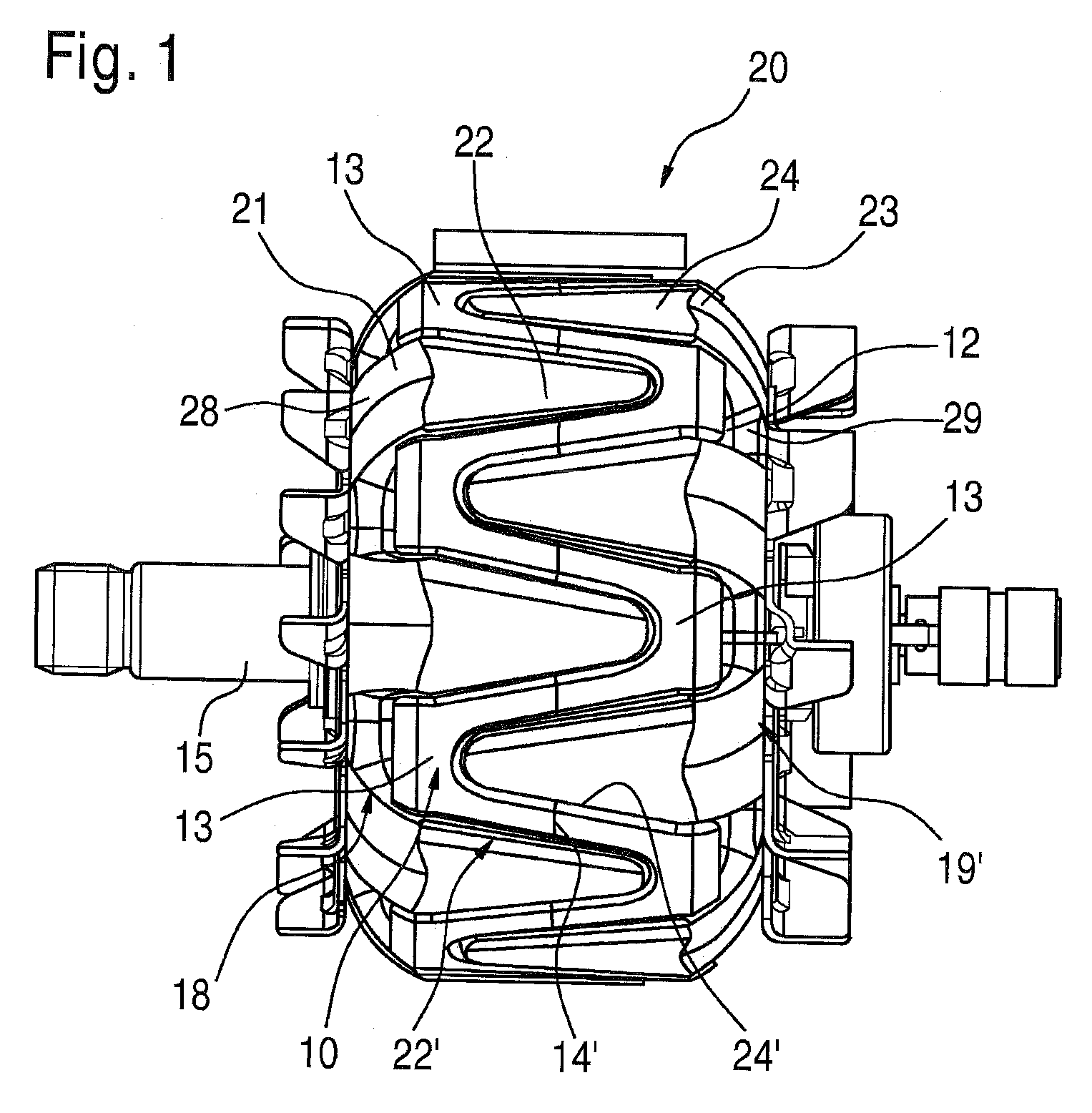
[0024]FIG. 1 shows a side view of a claw pole generator 20 according to the invention, with two pole wheel halves 21, 23 that are mounted on a drive shaft 15 and have clawlike magnet poles 22, 24. The magnet poles 22, 24 of the two pole wheel halves 21, 23 mesh with one another. Between the magnet poles 22, 24, there is an annular closure body 10. The pole wheel halves 21, 23 together with the closure body 10 form a rotor of the claw pole generator 20. For the sake of simplicity, only some of the elements are shown as examples with reference numerals.

[0025]The magnet poles 22, 24 are inserted by their tips into the closure body 10, so that the closure body 10 wraps at least in some regions around the magnet poles 22, 24 there, while the respective pole roots 28, 29 are free. The magnet poles 22, 24 each originate at respective mounting plates 18 and 19 located axially one on either side.

[0026]The magnet poles 22, 24 are covered on their lateral edges 22′ and 24′, respectively, by a ...


PUM


Abstract

The invention relates to a claw pole generator comprising a claw pole rotor, two magnet wheel halves (21, 23) which are mounted on a drive shaft (15) and are provided with claw-shaped magnet poles (22, 24) that mesh with each other, and an annular closing member (10) located between adjacent magnet poles (21, 23). The magnet wheel halves (21, 23) can be inserted into pockets (11) of the closing member (10) along with the magnet poles (22, 24) thereof such that the closing member (10) overlaps the magnet poles (22, 24) on the edge in at least some areas. Also disclosed is a closing member (10).

Description

PRIOR ART[0001]The invention is based on a claw pole generator as generically defined by the preamble to claim 1 and on a closure body for a claw pole generator as generically defined by the preamble to claim 11.[0002]In claw pole generators, it is known that annoying interference noises can arise in the rotor and stator if the air volumes between the clawlike magnet poles are excited to vibration as a consequence of protrusions and indentations on the stator and winding head geometry. To overcome this problem, claw pole closures are used, which provide the smoothest possible outer circumferential surface of the claw pole rotor.[0003]From German Patent Disclosure DE 196 42 784 A1 which defines this generic type, a claw pole generator is known that has two pole wheel halves, mounted on a drive shaft, that have clawlike magnet poles, and the magnet poles of the two pole wheel halves mesh with one another. An annular permanent-magnetic closure body is provided between adjacent magnet p...

Claims


Application Information

Patent Timeline
Patent Type & Authority Patents(United States)
IPC IPC(8): H02K1/22H02K21/12
CPCH02K1/243
Inventor LUTZ, HANS-JOACHIMGAMM, OLIVERBRAUN, HORST
Owner SEG AUTOMOTIVE GERMANY GMBH
Why Eureka
Try Eureka