Hot-stick capable cutout cover

a technology of hot-stick and cutout, which is applied in the direction of insulating bodies, cables, insulated conductors, etc., can solve the problems of increased installation time, increased difficulty in installing an independent (or loose) fastener with a hot-stick, and increased difficulty in installing an integral fastener

Active Publication Date: 2010-11-23
HUBBELL INC
View PDF37 Cites 24 Cited by
  • Summary
  • Abstract
  • Description
  • Claims
  • Application Information

AI Technical Summary

Benefits of technology

[0007]Another object is to provide a cutout cover having at least one grab point for connecting to a hot-stick tool so a lineman can remove the cover without risking electrical contact.
[0008]Still another object is to provide a flexible cutout cover that can withstand inclement weather without becoming dislodged atop the cutout.
[0010]A further object of the invention is to provide a fastener mechanism between the two sides of the cover where (1) one of the sides includes a keyhole shaped aperture with more than one radii for providing a secure locking relationship between the two sides of the cover and (2) the other includes a fastener receiving aperture with a radius larger than the smaller radius of the first side.

Problems solved by technology

When cutouts are installed in the field without a cover, they present a risk of electrical shock to wildlife and installers (linemen).
This presents two problems: (1) installation time is increased each time the installer must bring the end of the hot-stick back to his level, and (2) the level of difficulty of installing an independent (or loose) fastener with a hot-stick is much greater than installing an integral fastener.

Method used


Image

  • Hot-stick capable cutout cover
  • Hot-stick capable cutout cover
  • Hot-stick capable cutout cover

Examples


second embodiment

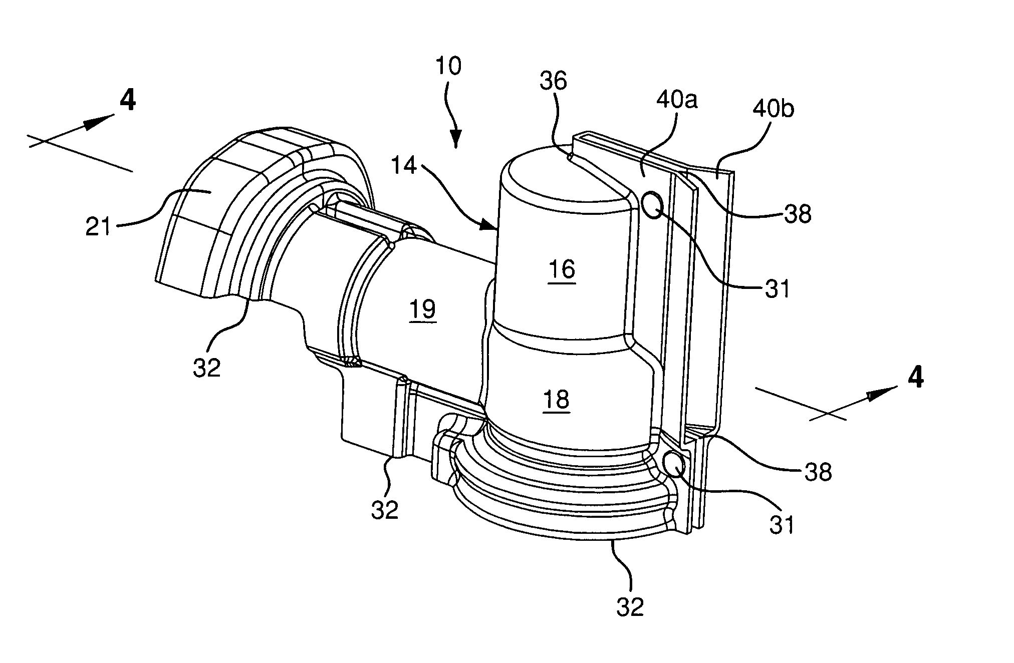
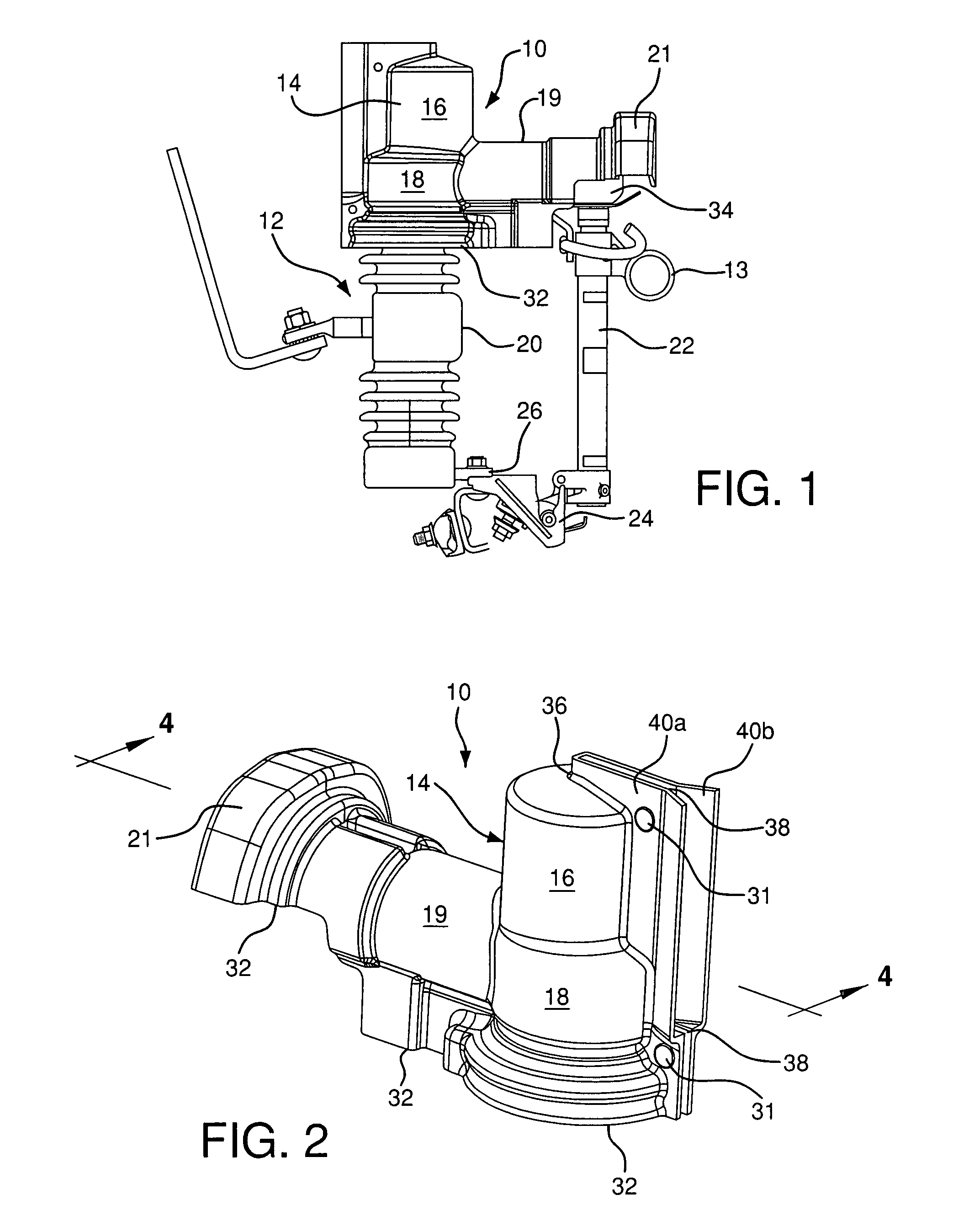
[0042]In the invention, seen in FIGS. 7-13, a cover 100 includes a variety of hot-stick grab points compatible with hot-stick tools for this type of installation. The hot-stick grab points are attachment points for the hot-stick tool so the lineman does not have to touch the cover 100 with his bare hands or rubber gloves. With the cover 10 of the previous embodiment lacking hot-stick grab points, the installer must wear rubber gloves to install the cover 10.

[0043]The overall design of this cover 100 is similar to the previous cover 10 with the exception of the hot-stick grab points and the fastener mechanism. Cover 100 includes a handle 150 extending from the neck 119. The grab point 140 is located on the end of the handle 150. The grab point 140 is substantially knob-shaped and projects from the columnar handle 150 towards the upper dome 116 of the cover 100.

first embodiment

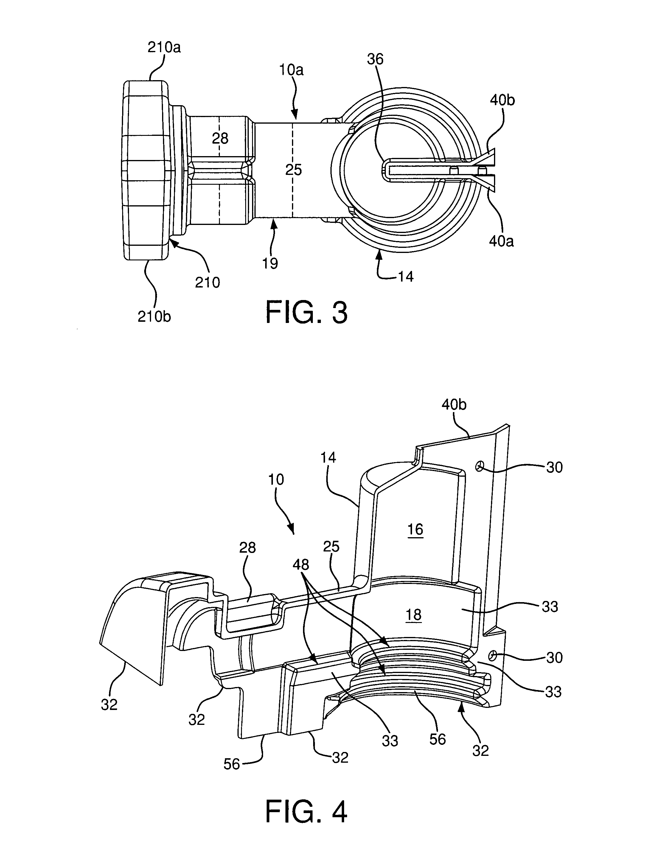
[0044]The type of fastener mechanism in this embodiment includes a first aperture 141, a second aperture or receiver 142, and a cone-shaped fastener 144. Similar to the first embodiment, the fastener mechanism retains the sides 140a, 140b in a closed position to withstand the opening and closing motion of the living hinge 136. Moreover, this connection further secures the cover 100 onto the cutout around the top of the insulator and prevents it from sliding off due to weather damage, etc.

[0045]First aperture 141 is disposed on side 140a of the top portion 114 and includes a substantially circular shape for accepting the cone-shaped fastener 144 and being received in an annular groove in the fastener. The head 145 of the fastener 144 is substantially cone-shaped to glide through the aperture 141 and the slit 138 towards the receiver 142 in the opposing side 140b.

[0046]The receiver 142 is substantially key-shaped for enabling easy installation of the fastener 144 with a hot-stick too...


PUM

PropertyMeasurementUnit
degree anglesaaaaaaaaaa
diametersaaaaaaaaaa
diameteraaaaaaaaaa

Abstract

A cutout cover includes an arcuate top portion covering an insulator having a closed top and an open bottom with a slit extending therebetween. A midsection can connect the top portion to an open end adapted to access the cutout. The top portion is bell-shaped with an upper and lower dome, two opposing sides, and a slit between the sides. A fastener mechanism is attached to the two opposing sides with an aperture disposed on each of the sides for receiving a fastener.

Description

FIELD OF THE INVENTION[0001]The present invention relates to a cutout cover for polymer and porcelain cutouts covering an electrical utility mechanism to protect wildlife from execution. More particularly, the invention relates to a flexible, yet sturdy cover, preferably having multiple hot-stick grab points and an integrated fastener mechanism installable with a hot-stick tool.BACKGROUND OF THE INVENTION[0002]When cutouts are installed in the field without a cover, they present a risk of electrical shock to wildlife and installers (linemen). Installations of most covers on the market require the removal of the stinger wire prior to installation. Some conventional covers can fit over a cutout without removing the stinger wire from the assembly, but those covers are multiple piece designs that must be installed while a lineman is wearing rubber gloves to protect against electrocution, thus requiring the lineman to be near the cutout via a ladder or bucket truck.[0003]There are at lea...

Claims


Application Information

Patent Timeline
Patent Type & Authority Patents(United States)
IPC IPC(8): H02B1/06H01B7/00H01B17/58
CPCH01B17/00H01H31/023H01H31/127H01H85/25
Inventor BRADFORD, LAWRENCE E.NARO, BRIAN A.
Owner HUBBELL INC
Why Eureka
Try Eureka