
Industrial computer chassis structure with power source disposed centrally

a technology of computer chassis and power supply, applied in the field of industrial computers, can solve the problems of increasing complexity and cost in structural design, and the power supply is not disposed at the most appropriate position in the computer chassis

Active Publication Date: 2010-11-23
SUPER MICRO COMP
View PDF14 Cites 25 Cited by
  • Summary
  • Abstract
  • Description
  • Claims
  • Application Information

AI Technical Summary

Benefits of technology

The invention is a computer chassis structure with a centrally located power source. The structure has two motherboard sections with a power source arrangement section in between. Each motherboard can be placed in a motherboard tray and is close to the power source arrangement section, allowing for both hardware connection and software system control. The technical effect of this structure is that all motherboards can be close to the power source arrangement section, making it easy to achieve common usage for both hardware connection and software system control.

Problems solved by technology

According to prior arts, their power supplies are not disposed at most appropriate position in the computer chassis.
Therefore, when a malfunction problem occurs to one power supply, although the supplied watts of other power supplies can be raised, through the control of a software system, however, the difficulty to integrate the hardware in the chassis is raised due to the poor design of the disposition structure, the result even causing the increases of complexity and cost in terms of structural design.

Method used


Image

  • Industrial computer chassis structure with power source disposed centrally
  • Industrial computer chassis structure with power source disposed centrally
  • Industrial computer chassis structure with power source disposed centrally

Examples


Embodiment Construction

[0013]In cooperation with attached drawings, the technical contents and detailed description of the present invention are described thereinafter according to a preferable embodiment, not used to limit its executing scope. Any equivalent variation and modification made according to appended claims is all covered by the claims claimed by the present invention.

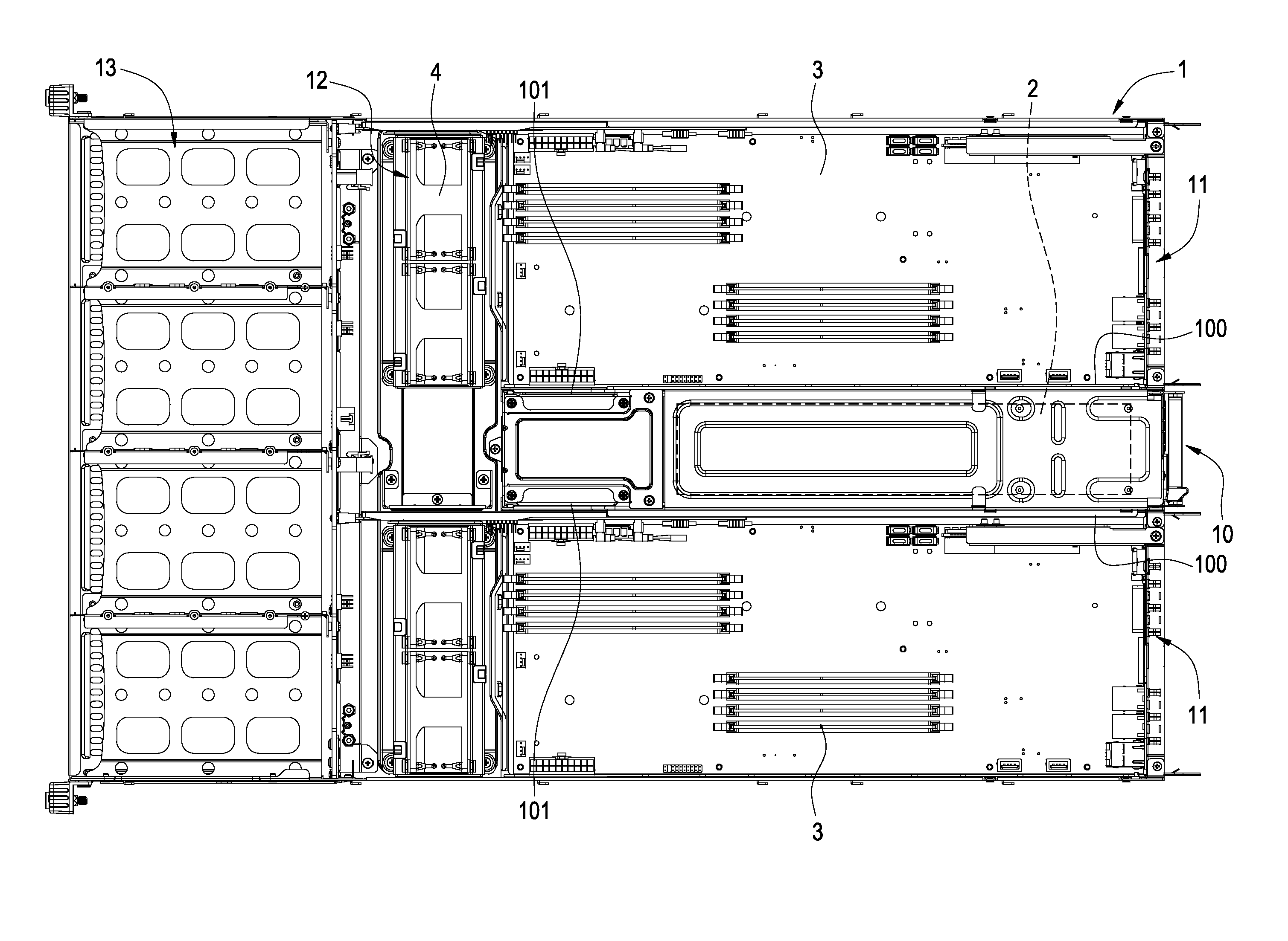
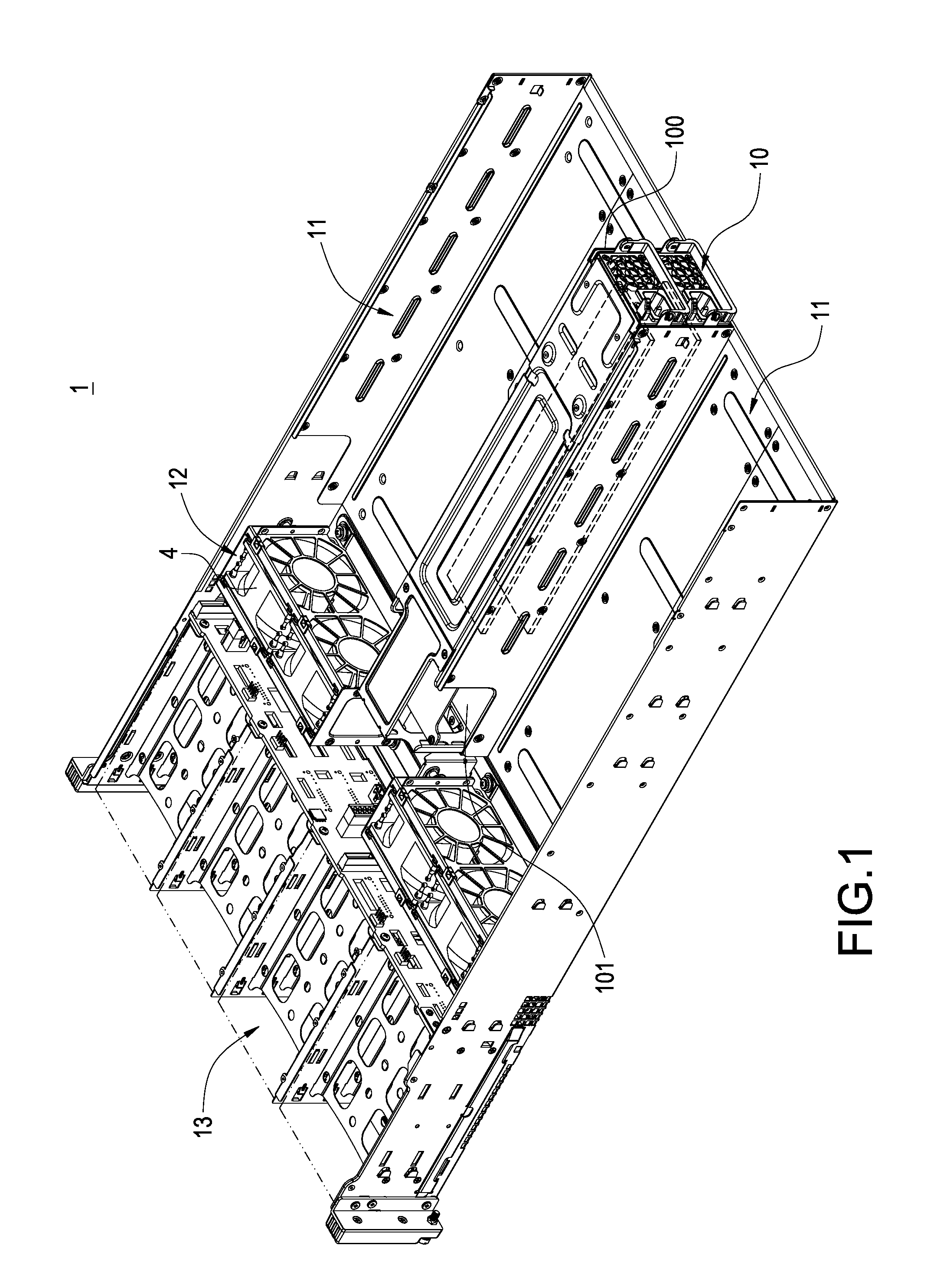
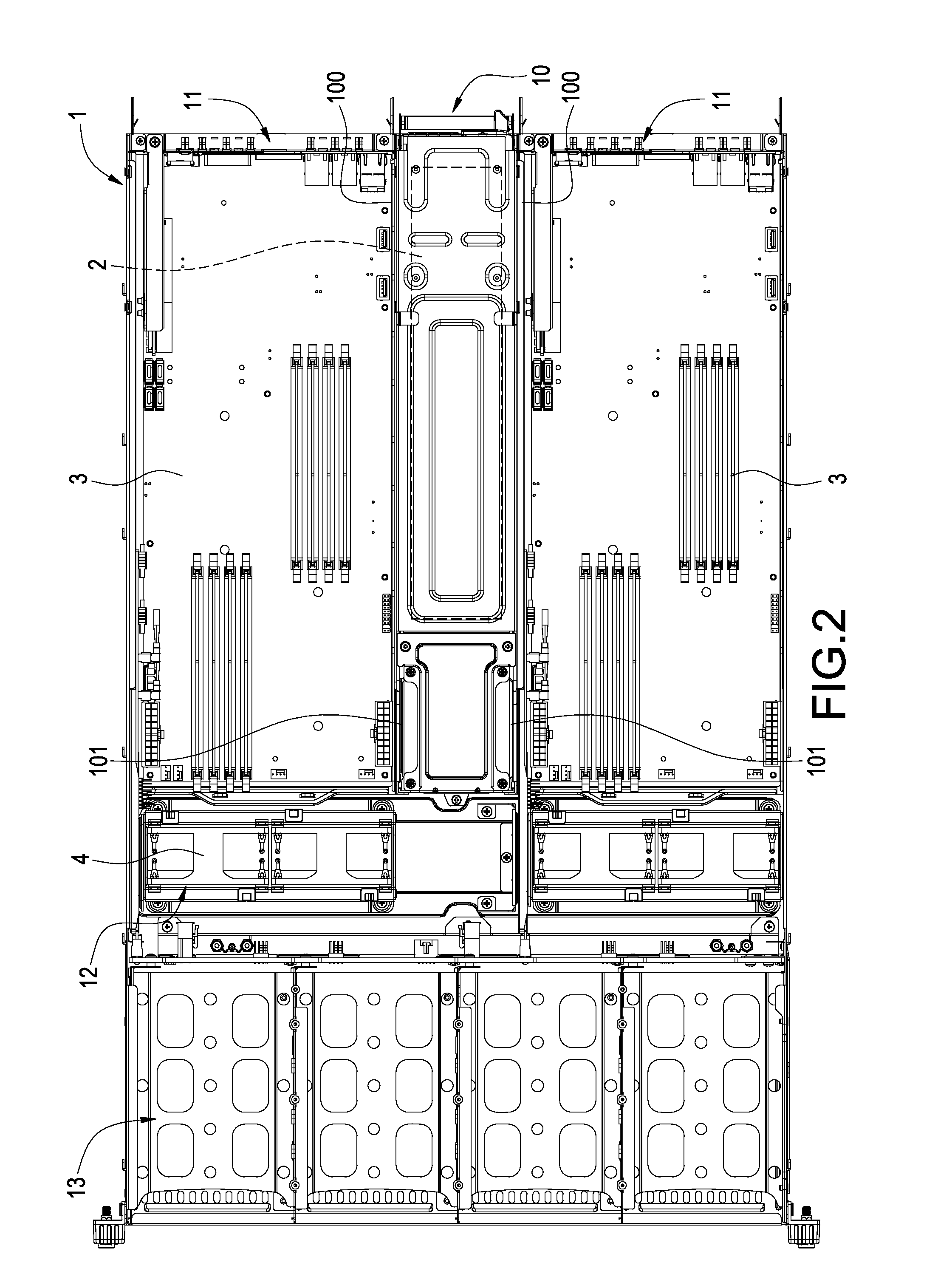
[0014]Please refer to FIG. 1 and FIG. 2, respectively showing a perspective view of an internal structure of the invention and a top plane illustration of the invention. The invention is to provide an industrial computer chassis structure with power source disposed centrally, having a chassis shell 1 of industrial computer, at least one power source arrangement section 10 partitioned in the chassis shell 1 and at least two motherboard sections 11 respectively located at two sides of the power source arrangement section 10, whereby aforementioned each motherboard section 11 can be close to the power source arrangement section 10 a...


PUM


Abstract

An industrial computer chassis structure is mainly to partition at least two motherboard sections in the shell of the computer chassis, in each of which a motherboard tray capable of being pulled and drawn is arranged and is provided for placing a motherboard therein. Meanwhile, the two motherboard sections are horizontally disposed by being parallel with each other, in the space between which a power source arrangement section is formed. The power source arrangement section is provided for arranging power supplies of the computer therein. Through this kind of disposition structure, all motherboards in the motherboard sections can be close to the power source arrangement section as near as possible, such that a function of common usage can be achieved for both the hardware connection and the software system control.

Description

BACKGROUND OF THE INVENTION[0001]1. Field of the Invention[0002]The present invention in general relates to an industrial computer, in particular, to an industrial computer chassis structure which is applied to a server and has a power source disposed centrally.[0003]2. Description of Prior Art[0004]Since of a daily progress of computer industry and a daily reliance on industry computer system, the requirement asked by enterprises onto server system is also heightened relatively. Responding to the speedy growth, many enterprises usually adopt the integration of numerous servers. Thereby, the gigantically produced data or the very-busy internet interaction can be handled and the future requirement concerning the expansion and upgrade of the server system can also be responded.[0005]In addition, common industrial computer is usually operated in a long period. Once a malfunction problem occurs to any hardware, enterprise usually requires that the hardware assembly has to be repaired or...

Claims


Application Information

Patent Timeline
Patent Type & Authority Patents(United States)
IPC IPC(8): G06F1/16
CPCG06F1/184G06F1/187G06F1/188
Inventor LIN, TE-CHANG
Owner SUPER MICRO COMP
Learn More