Bicycle shift controller
a shift controller and bicycle technology, applied in the direction of linear movement shafts, axle suspensions, shafts and bearings, etc., can solve the problems of limited use of bicycle shift controllers and inability to realize the advantages of assigning, and achieve the effect of improving the functionality of shifting
- Summary
- Abstract
- Description
- Claims
- Application Information
AI Technical Summary
Benefits of technology
Problems solved by technology
Method used
Image
Examples
second embodiment
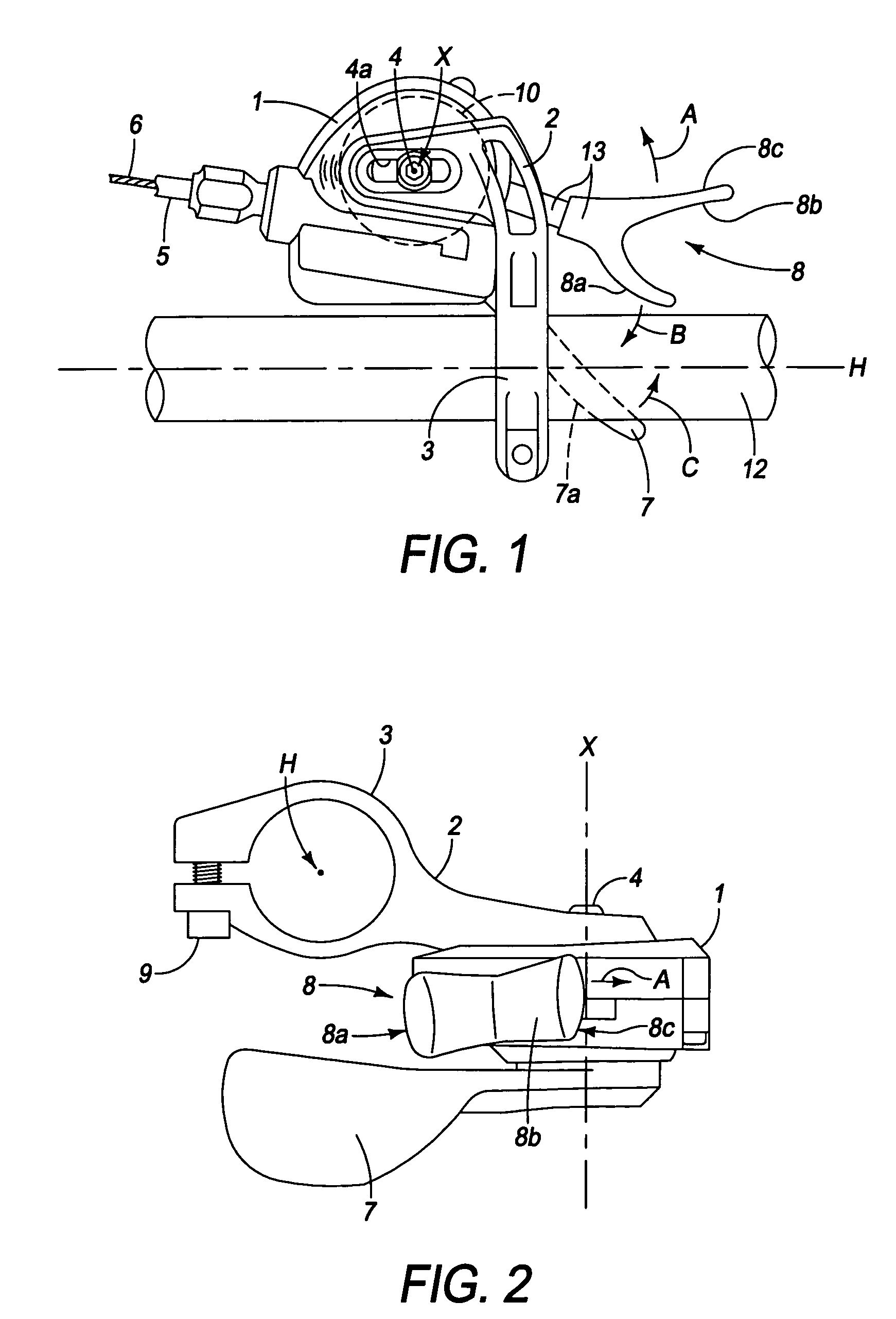
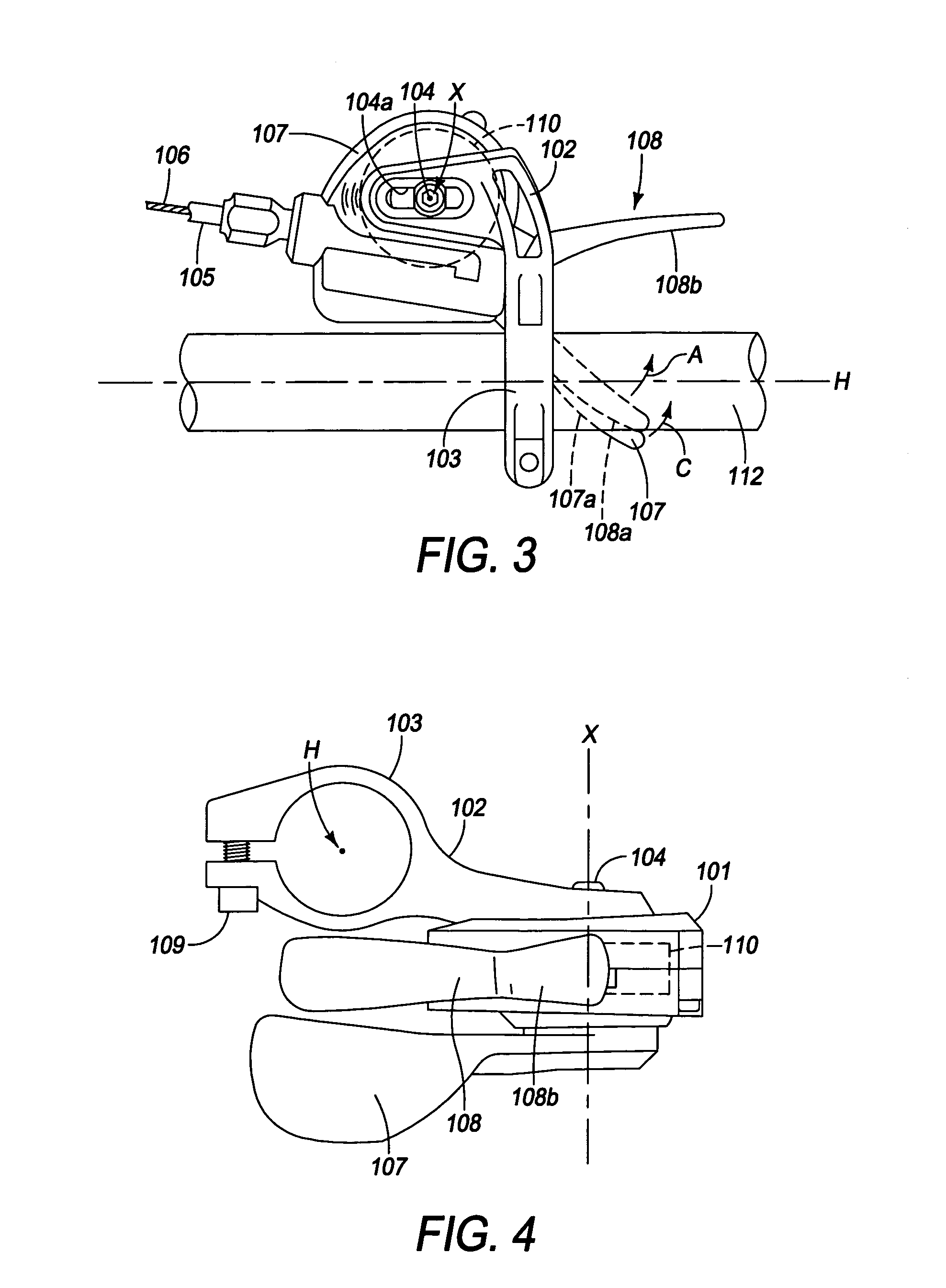
[0054]Referring now to FIGS. 3 and 4, a bicycle shift controller in accordance with a second embodiment will now be explained. The second embodiment shown in the FIG. 3 and FIG. 4 differs from the first embodiment only by the design of the release lever 8 of the first embodiment has been changed in this second embodiment. In view of the similarity between the first and second embodiments, the parts of the second embodiment that are identical to the parts of the first embodiment will be given the same reference numerals as the parts of the first embodiment but with the numbering increased by 100. Thus, the descriptions of the parts of the second embodiment that are identical to the parts of the first embodiment may be omitted for the sake of brevity.
[0055]The bicycle shift controller shown in FIGS. 3 and 4 includes a housing 101, a bracket 102 with a clamping portion 103 and a fixing bolt 104 connecting the bracket 102 to the housing 101 via an elongated hole 104a in the bracket 102....
third embodiment
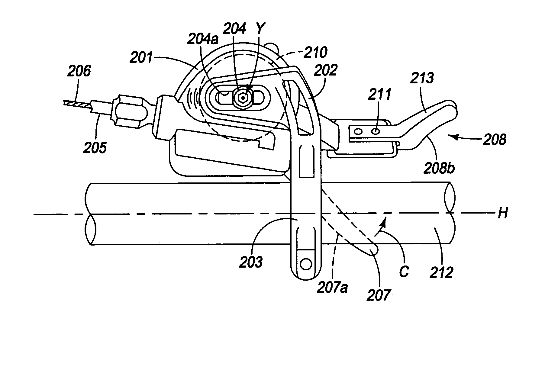
[0058]Referring now to FIGS. 5 and 6, a bicycle shift controller in accordance with a third embodiment will now be explained. The third embodiment differs from the first embodiment by the design of the release lever 8 of the first embodiment has been changed in this third embodiment, the connection of the cable release lever 8 to the takeup member 10 has been changed in this third embodiment, and the pivot axis X of the cable release lever 8 has been changed in this third embodiment. In view of the similarity between the first and third embodiments, the parts of the third embodiment that are identical to the parts of the first embodiment will be given the same reference numerals as the parts of the first embodiment but with the numbering increased by 200. Thus, the descriptions of the parts of the third embodiment that are identical to the parts of the first embodiment may be omitted for the sake of brevity.
[0059]The bicycle shift controller shown in FIGS. 5 and 6 includes a housing...
fourth embodiment
[0064]Referring now to FIG. 7, a bicycle shift controller in accordance with a fourth embodiment will now be explained. The fourth embodiment differs from the third embodiment by the design of the cable release lever 208 of the third embodiment has been changed in this fourth embodiment, i.e., the first operating portion and the second operating portion are formed integrally. In view of the similarity between the first and fourth embodiments, the parts of the fourth embodiment that are identical to the parts of the first embodiment will be given the same reference numerals as the parts of the first embodiment but with the numbering increased by 100 from the third embodiment. Thus, the descriptions of the parts of the fourth embodiment that are identical to the parts of the first embodiment may be omitted for the sake of brevity.
[0065]The bicycle shift controller shown in FIG. 7 includes a housing 301, a bracket 302 with a clamping portion 303 and a fixing bolt 304 connecting the bra...
PUM
 Abstract
Description
Claims
Application Information
 - R&D
- Intellectual Property
- Life Sciences
- Materials
- Tech Scout
- Unparalleled Data Quality
- Higher Quality Content
- 60% Fewer Hallucinations
Browse by: Latest US Patents, China's latest patents, Technical Efficacy Thesaurus, Application Domain, Technology Topic, Popular Technical Reports.
© 2025 PatSnap. All rights reserved.Legal|Privacy policy|Modern Slavery Act Transparency Statement|Sitemap|About US| Contact US: help@patsnap.com


