Window frame

a window frame and window frame technology, applied in the direction of rod connections, mechanical devices, fastening means, etc., can solve the problems of difficult assembly process, frequent widened or separated joining regions of the window frame, and difficulty for a sole worker to grasp and weld or screw the sill and jamb frame, etc., to prevent the effect of external force deformation and new corner angles

Inactive Publication Date: 2010-12-07
SIBBETT PETER
View PDF22 Cites 29 Cited by
  • Summary
  • Abstract
  • Description
  • Claims
  • Application Information

AI Technical Summary

Benefits of technology

[0016]The present invention is conceived to solve the aforementioned problems in the prior art. An object of the present invention is to provide a window frame, which is configured so that an assembling process of sill and jamb frames can be performed simply and smoothly and the joining regions thereof are not widened or separated, and which has novel corner angles allowing deformation caused by external force to be prevented.

Problems solved by technology

Thus, there is a problem in that the assembling process is difficult.
However, it is very difficult for a sole worker to grip and weld or screw the sill and jamb frames.
In particular, when the sill and jamb frames are directly joined to each other, there is a problem in that the joining region thereof is frequently widened or separated with ease.
However, the bracket is formed by bending a general metal thin plate, so that it does not have high torsional or bending strength.
Thus, there is a problem in that the bracket is easily bent by external force and thus cannot reinforce the joining regions sufficiently.
In particular, the bracket is configured so that both ends thereof are inserted into the sill frame and one of the jamb frames (or two of the jamb frames), so that it should have a very small thickness, which results in very weak strength.
Further, since the conventional reinforcement is made of metal, its entire weight is heavy.
However, since such a structure conducts external heat directly to the indoor space, there is a problem in that a heat protection effect is deteriorated.

Method used


Image

  • Window frame
  • Window frame
  • Window frame

Examples


Embodiment Construction

[0043]Hereinafter, a preferred embodiment of a window frame according to the present invention will be described in detail referring to FIGS. 1 to 10.

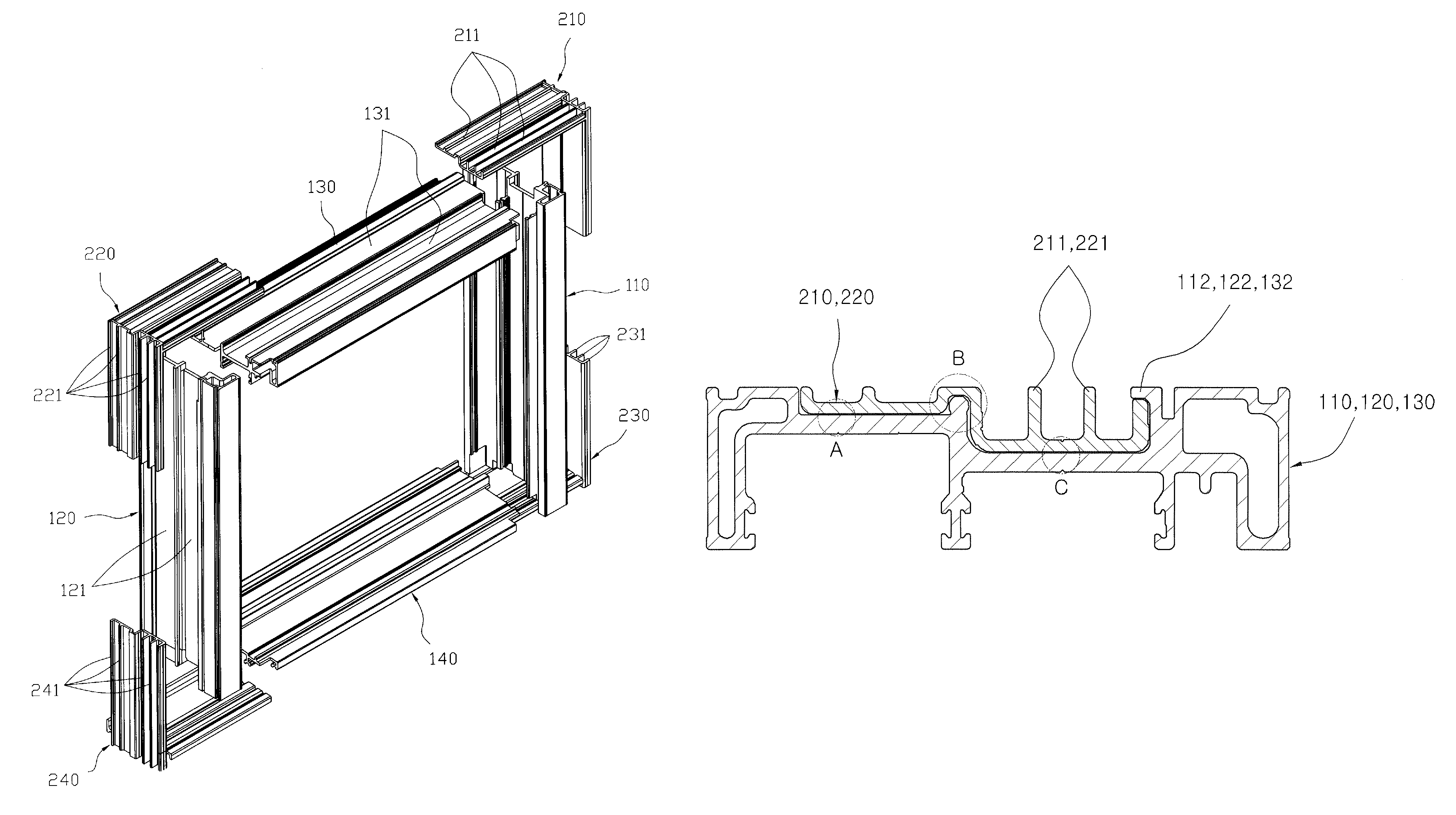
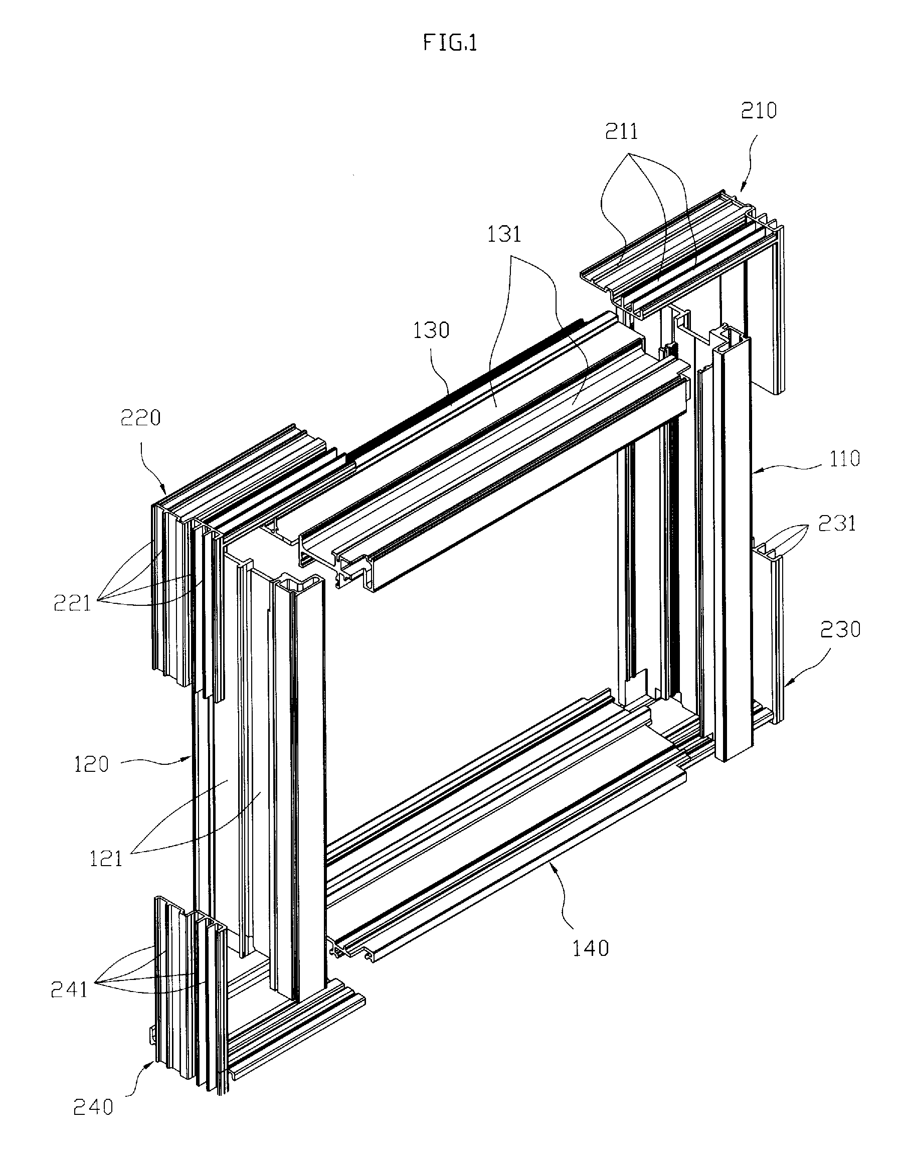
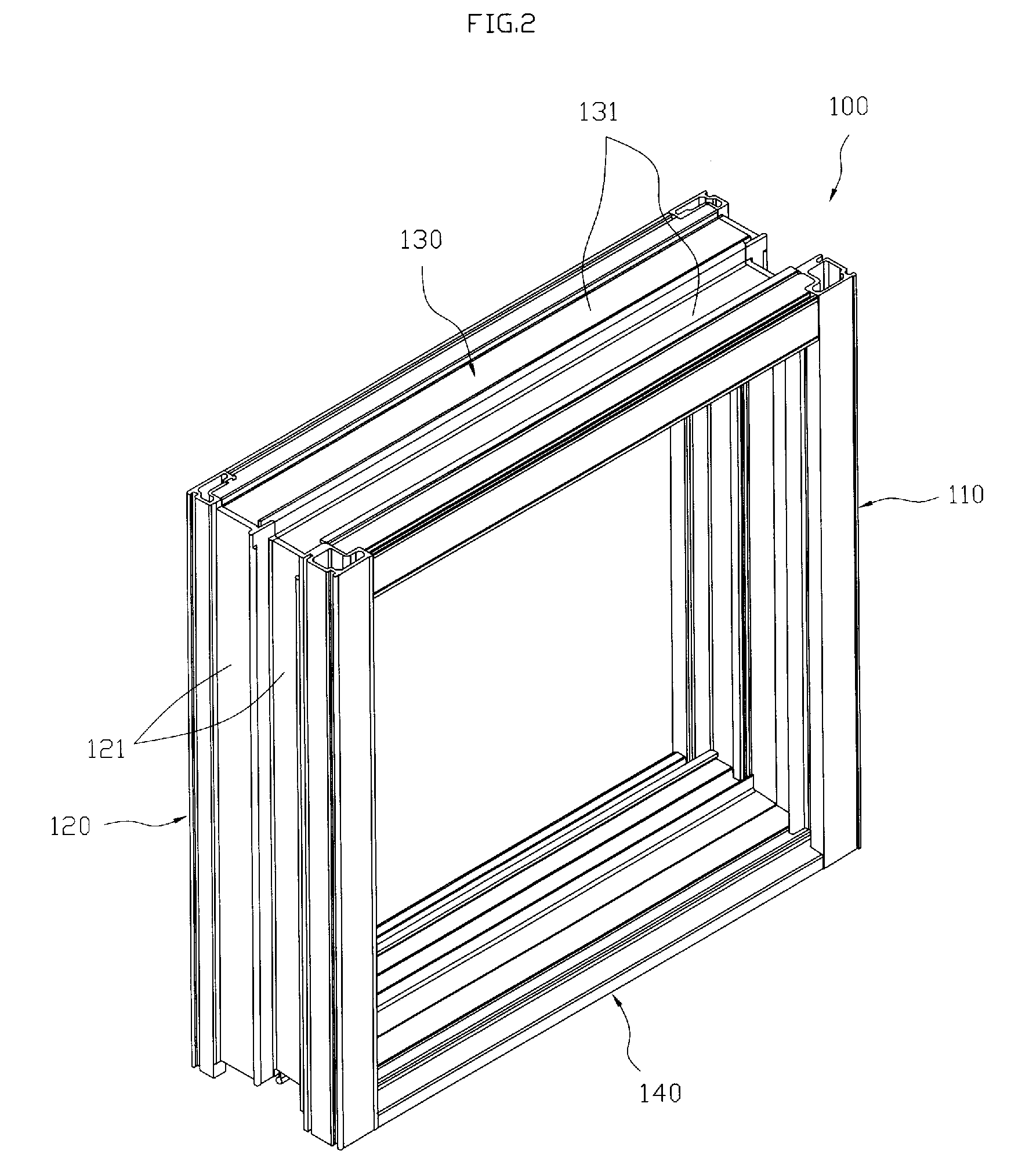
[0044]The window frame according to the preferred embodiment of the present invention includes a frame unit 100 having a rectangular frame shape, and a plurality of corner angles 210, 220, 230 and 240, each of which will be explained below in detail.

[0045]First, the frame unit 100 is formed in such a manner that a plurality of jamb frames 110, 120 and 130 and a sill frame 140 are assembled into a rectangular frame shape as shown in FIGS. 1 and 2. A window (not shown) is installed in the frame unit 100 to be slidable and swingable.

[0046]Here, the jamb frames 110, 120 and 130 are classified into the pair of side jamb frames 110 and 120 defining both side ends of the frame unit 100 and the upper jamb frame 130 defining an upper end of the frame unit 100.

[0047]The jamb and sill frames 110, 120, 130 and 140 are manufactured by a drawing or ...


PUM


Abstract

The present invention relates to a window frame. According to the present invention, there is provided a window frame, which comprises: a frame unit having a pair of side jamb frames for defining both side ends of the frame unit, an upper jamb frame for defining an upper end thereof, and a sill frame for defining a lower end thereof coupled to each other to have a rectangular frame shape, the frame unit having at least one receiving groove formed in an outer wall surface thereof along a length direction thereof; and corner angles coupled to the frame unit to surround the outer wall surface of the frame unit at corners thereof, each of the corner angles having a concavo-convex portion to be received in the receiving groove, the corner angle having at least one rib protruding from an outer wall surface thereof along a length direction thereof.

Description

RELATED APPLICATION[0001]This application claims the benefit of U.S. Provisional application No. 60 / 899,685. The entire contents of the above-identified applications are hereby incorporated by reference in their entirety.BACKGROUND OF THE INVENTION[0002]1. Field of the Invention[0003]The present invention relates to a window frame, and more particularly, to a window frame, which is configured so that an assembling process can be performed simply and smoothly, and which has novel corner angles allowing conduction of external heat to be minimized and torsional deformation to be prevented.[0004]2. Description of the Related Art[0005]Generally, a window frame is to separate a dwelling space and an un-dwelling space from each other, and various kinds of windows having a door glass installed thereto are slidably installed to the window frame.[0006]Such a window frame includes a sill frame defining a lower end and installed along the ground, and jamb frames defining an upper end and both s...

Claims


Application Information

Patent Timeline
Patent Type & Authority Patents(United States)
IPC IPC(8): E04C2/38
CPCE06B3/9687E06B3/9642E06B3/4609Y10T403/555
Inventor SIBBETT, PETER
Owner SIBBETT PETER
Why Eureka
Try Eureka