Sensor attachment mechanism for fluid pressure cylinder

a technology of fluid pressure cylinder and sensor, which is applied in the direction of fluid pressure measurement, machines/engines, instruments, etc., can solve the problems of inability to attach position detecting sensors, physical interference of position detecting sensors with each other in the groove mechanism, and limited use of tie-rod-type mechanisms

Active Publication Date: 2006-02-09
SMC CORP
View PDF4 Cites 12 Cited by
  • Summary
  • Abstract
  • Description
  • Claims
  • Application Information

AI Technical Summary

Benefits of technology

[0022] The above sensor attachment mechanism according to the present invention is a rail-type mechanism, which is advantageous in disposin...

Problems solved by technology

Of these mechanisms, the use of the tie-rod-type mechanism is limited to fluid pressure cylinders having tie rods.
If, on the other hand, the cylinder has a short stroke, the position detecting sensors interfere physically with each other in the groove mechanism.
For a compact cylinder, particularly, position d...

Method used


Image

  • Sensor attachment mechanism for fluid pressure cylinder
  • Sensor attachment mechanism for fluid pressure cylinder
  • Sensor attachment mechanism for fluid pressure cylinder

Examples


Embodiment Construction

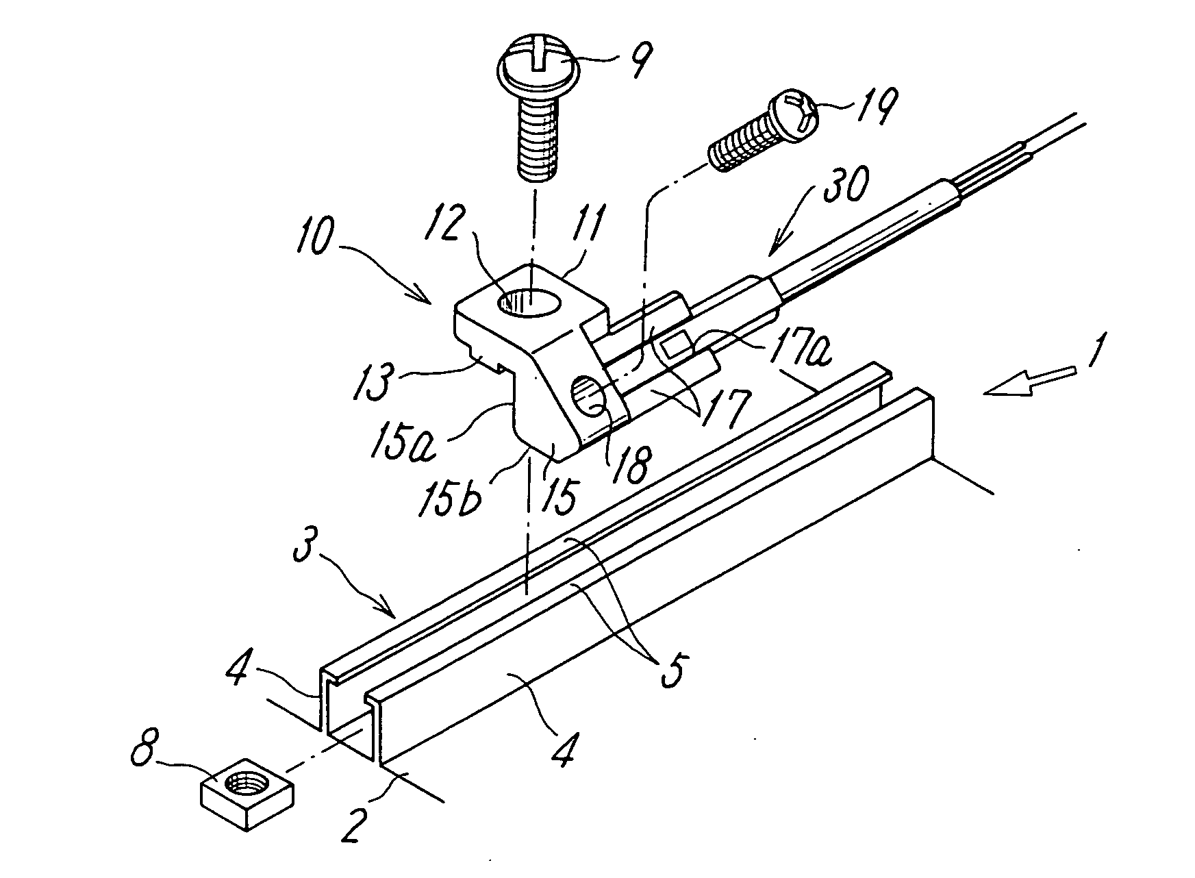
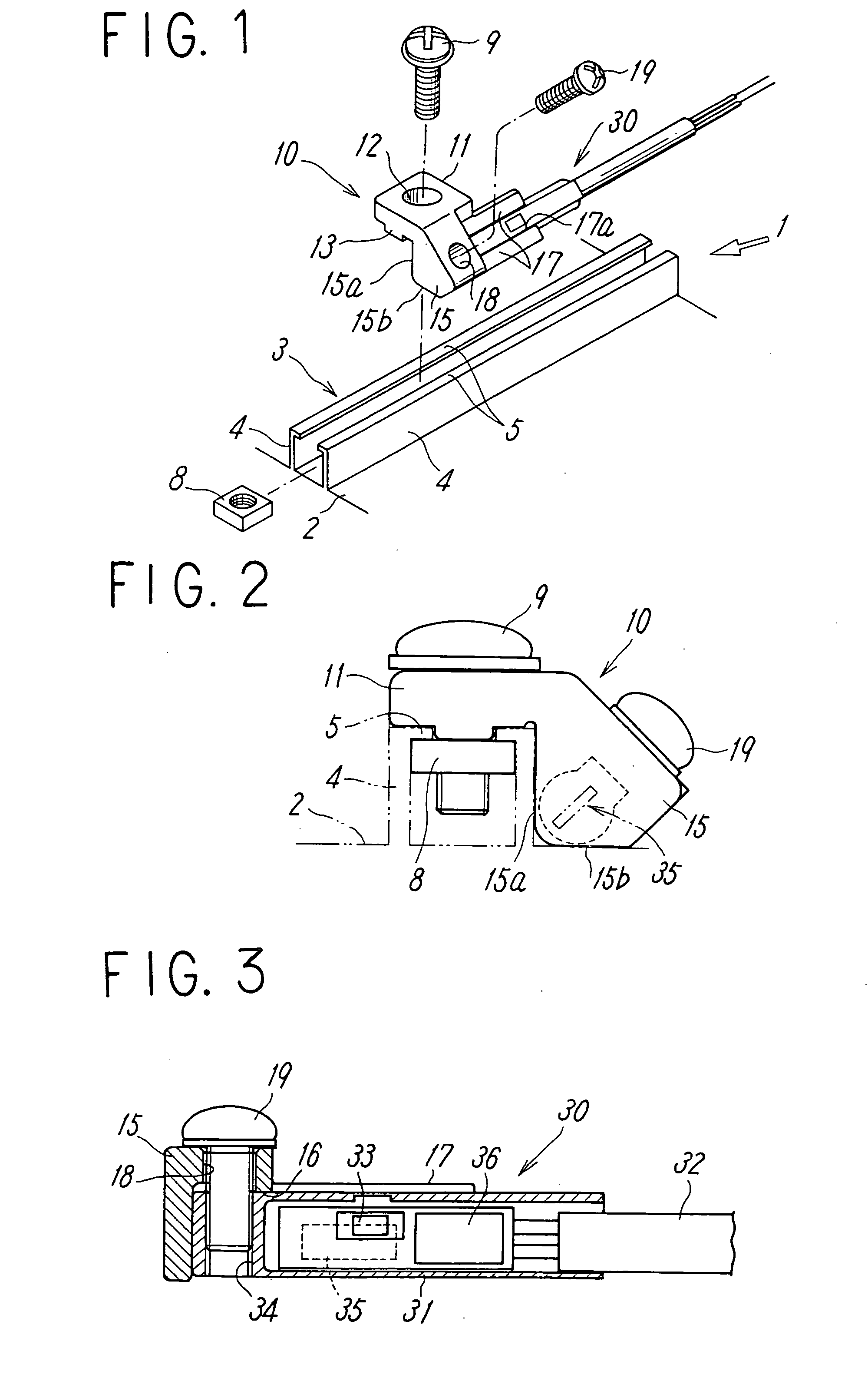
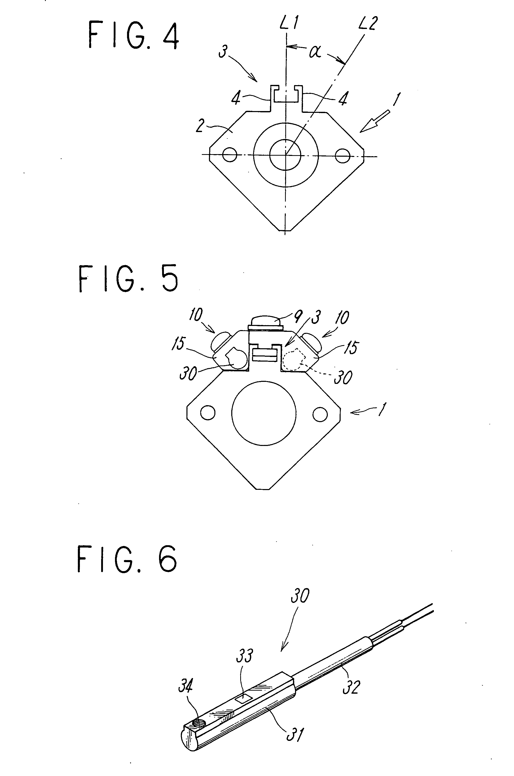
[0033] FIGS. 1 to 4 illustrate a sensor attachment mechanism according to an embodiment of the present invention.

[0034] Referring to, for example, FIGS. 1, 2, and 4, a fluid pressure cylinder 1 provided with a position sensing switch according to the present invention has a grooved rail 3 protruding from the outer surface of a cylinder tube 2 along the length thereof. A position detecting sensor 30 is attached to the rail 3 with a sensor holder 10. This position detecting sensor 30 has directivity in sensing the operating position of a piston having a position detecting magnet (not shown in the drawings). The position detecting magnet is a ring-shaped magnet that is fitted around the piston of the fluid pressure cylinder 1 and is magnetized such that the magnetic flux therefrom is directed in the axial direction of the cylinder 1.

[0035] The cylinder tube 2 is made of a nonmagnetic material such as aluminum, and the grooved rail 3 is formed integrally with the outer surface of the ...


PUM


Abstract

[Object] To provide a sensor attachment mechanism capable of attaching a position detecting sensor having directivity in a proper direction to a fluid pressure cylinder having a rail extending along the length of a cylinder tube on the outer surface thereof.
[Solving Means] A position detecting sensor for sensing the operating position of a piston is attached with a sensor holder to a grooved rail extending along the length of a cylinder tube on the outer surface thereof. The position detecting sensor has directivity in magnetic detection. The sensor holder includes a base mounted on the rail and a sensor holding part extending from the base. The sensor holding part is close to or in contact with the surface of the cylinder tube outside rail walls. The sensor holding part has a holding guide for holding the position detecting sensor in a direction parallel to the axis line of the cylinder such that the directivity of the sensor in the magnetic detection is directed to substantially the center of the cylinder.

Description

TECHNICAL FIELD [0001] The present invention relates to a sensor attachment mechanism for attaching a position detecting sensor to a fluid pressure cylinder having a rail disposed on the outer surface of a cylinder tube in the longitudinal direction. BACKGROUND ART [0002] A position detecting sensor is attached to a fluid pressure cylinder to determine the operating position of a piston. The position detecting sensor is provided outside the cylinder to correspond to a magnet attached to the piston in the cylinder. [0003] According to the forms of fluid pressure cylinders, conventional mechanisms for attaching a position detecting sensor include a rail-type mechanism in which a position detecting sensor is attached with a sensor holder to a rail disposed on the outer surface of a cylinder tube in the longitudinal direction, a tie-rod-type mechanism in which a sensor holder is attached using tie rods connecting the end covers of a cylinder tube, and a groove-type mechanism in which a ...

Claims


Application Information

Patent Timeline
IPC IPC(8): H01F5/00
CPCF15B15/2807G01D11/30G01D5/145F15B15/2892F15B15/02
Inventor TERASAKI, ATSUSHI
Owner SMC CORP
Why Eureka
Try Eureka