Electrooptical device, electronic device and manufacturing method of electrooptical device

An electro-optic device and manufacturing method technology, applied to identification devices, optics, nonlinear optics, etc., capable of solving problems such as floating from a liquid crystal display panel or light guide plate, LED luminance reduction, damage, etc.

Active Publication Date: 2005-03-23
BOE TECH GRP CO LTD
View PDF0 Cites 16 Cited by
  • Summary
  • Abstract
  • Description
  • Claims
  • Application Information

AI Technical Summary

Problems solved by technology

[0006] However, since the above-mentioned liquid crystal display device uses double-sided tape to fix the liquid crystal display panel or FPC to the light guide plate or reflector, etc., in a high-temperature environment, due to the influence of heat, the double-sided tape will be removed from the light guide plate or FPC. Since the reflective sheet is peeled off, the FPC or reflective sheet may float from the liquid crystal display panel or light guide plate.
Especially for FPCs equipped with LEDs, since its floating will cause the optical axis of the LEDs to deviate from the central axis of the light guide plate, the luminance of the LEDs will decrease.
[0007] In addition, in electronic equipment equipped with such a liquid crystal display device, there may be a problem that the liquid crystal display panel is bent or damaged due to dropping.

Method used


Image

  • Electrooptical device, electronic device and manufacturing method of electrooptical device
  • Electrooptical device, electronic device and manufacturing method of electrooptical device
  • Electrooptical device, electronic device and manufacturing method of electrooptical device

Examples


Embodiment 1

[0034] Next, preferred embodiments of the present invention will be described with reference to the accompanying drawings. In addition, in the following description, a liquid crystal display device will be described as an example of the electro-optical device according to Embodiment 1 of the present invention.

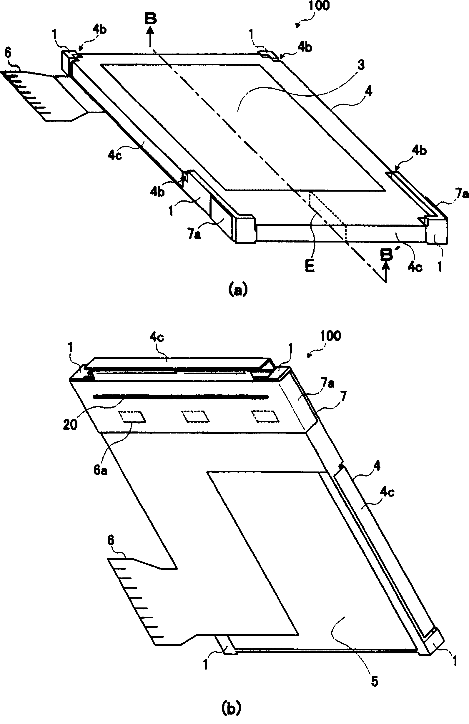
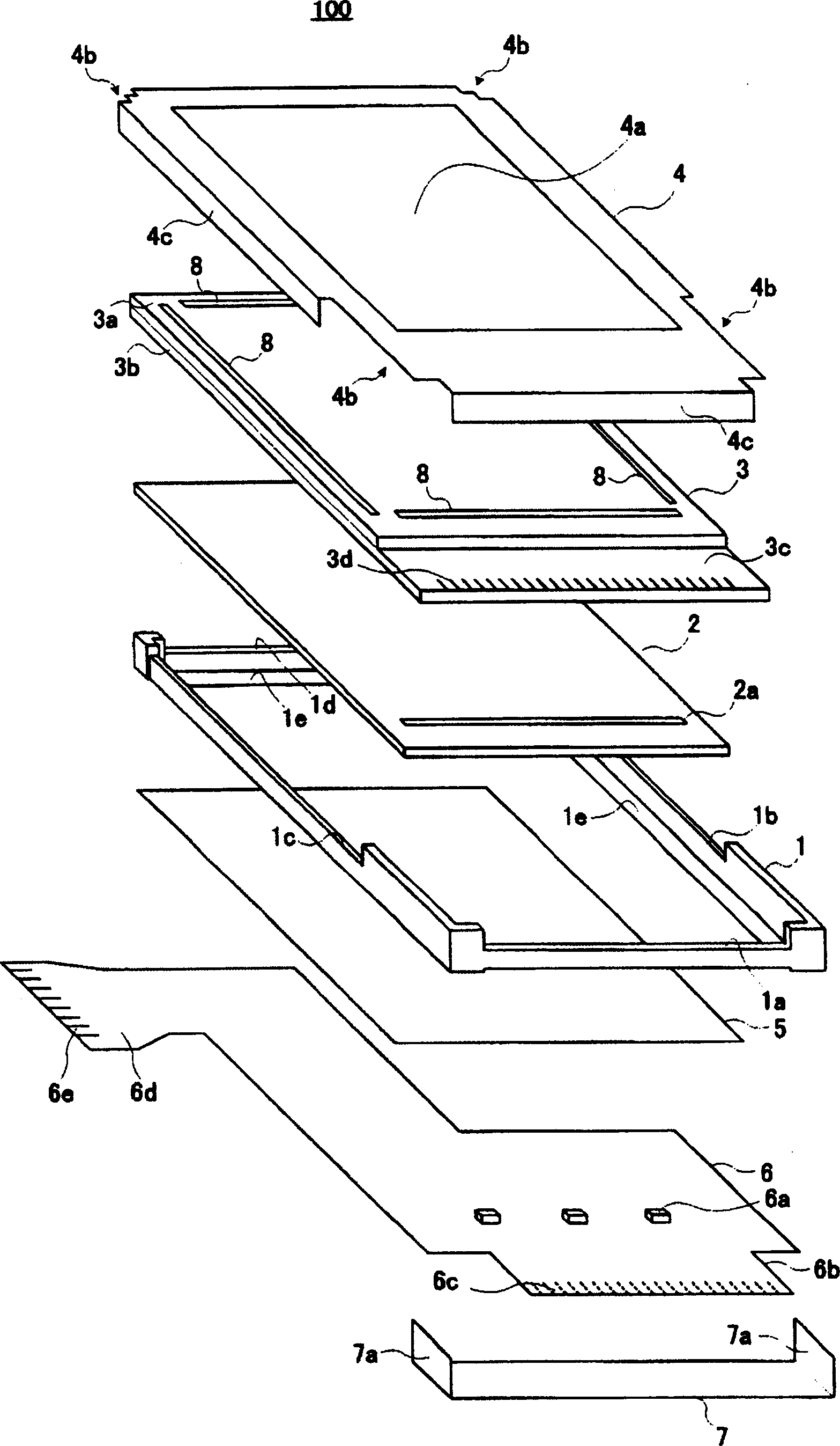
[0035] figure 1 It is a perspective view showing a schematic configuration of a liquid crystal display device according to Embodiment 1 of the present invention. figure 1 (a) shows the display part side (top side) of the liquid crystal display device 100, figure 1 (b) shows the back side. in addition, figure 2 express figure 1 An exploded perspective view of the liquid crystal display device 100 shown.

[0036] Such as figure 1 and figure 2 As shown, the liquid crystal display device 100 has, from figure 2 The upper frame 4, the liquid crystal display panel 3, the light guide plate 2, the middle frame 1, the reflection sheet 5, the FPC 6 and the lower frame 7 ...

Embodiment 2

[0052] Next, the configuration and the like of the liquid crystal display device according to Embodiment 2 of the present invention will be described. In the following, the same components as those of the liquid crystal display device 100 of the first embodiment are denoted by the same reference numerals, and description thereof will be omitted.

[0053] Figure 5 It is a perspective view showing a schematic configuration of a liquid crystal display device 200 according to Embodiment 2 of the present invention. Figure 5 (a) shows the display part side (top side) of the liquid crystal display device 200, Figure 5 (b) shows the back side. Additionally, Figure 6 shows Figure 5 An exploded perspective view of the liquid crystal display device 200 shown.

[0054] Such as Figure 5 As shown in FIG. 6, the liquid crystal display device 200 of Embodiment 2 has an upper frame 4, a liquid crystal display panel 3, a light guide plate 2, a middle frame 1, a reflection sheet 5, an ...


PUM


Abstract

To prevent a liquid crystal display panel from bending or breaking owing to falling and to prevent an FPC from floating by arranging upper and lower frames which are made of metal at proper positions of an electrooptical device. An electro-optical device comprises: an upper frame formed of a metal having an opening formed therein and having open portions formed in at least two corners thereof; an electro-optical panel having an electro-optical substance sealed between a pair of plates and arranged below the upper frame; a light guide plate arranged below the electro-optical panel; and an intermediate frame having a frame shape, arranged below the light guide plate, and being applied to support the electro-optical panel and the light guide plate. The electro-optical panel and the light guide plate is sandwiched between the upper frame and the intermediate frame. The peripheral edge along the four sides of the electro-optical panel is bonded to the upper frame by an adhesion element, and at least two corners of the intermediate frame are exposed in the open portions of the upper frame.

Description

technical field [0001] The present invention relates to an electro-optical device such as a liquid crystal display device, a manufacturing method thereof, and an electronic device equipped with the electro-optic device. Background technique [0002] In recent years, electro-optic devices, such as liquid crystal display devices, have been widely used in electronic equipment such as mobile phones. Generally, a transflective liquid crystal display device mounted on a portable electronic device is composed of a liquid crystal display panel, a light guide plate, a circuit or a light emitting diode (Light Emitting Diode: LED) equipped with a signal for driving the liquid crystal display panel. ) and other light sources such as flexible printed circuit boards (Flexible Printed Circuit hereinafter referred to as FPC), reflectors, and housings. [0003] As an example of the manufacturing method of such a liquid crystal display device, at first, the lower surface of the liquid crysta...

Claims


Application Information

Patent Timeline
Patent Type & Authority Applications(China)
IPC IPC(8): G02F1/1333G02F1/13G02F1/1335G02F1/13357G09F9/00
CPCG02F2001/133325G02F1/133615G02F1/133308G02F2001/133317G02F1/13452G02F1/133317G02F1/133325G02F1/1333
Inventor 樱井慎二高林和典百濑宪秀荒深奈美
Owner BOE TECH GRP CO LTD
Why Eureka
Try Eureka