Shielded connector

a technology of shielding connectors and connectors, applied in the direction of couplings/cases, coupling devices, connections effected by permanent deformation, etc., can solve the problem of complicated assembly and expensive manufacturing, and achieve the effect of simplifying the manufacture of the components required for the connectors and cost-efficient manufacturing

Active Publication Date: 2010-12-07
HARTING ELECTRIC GMBH & CO KG
View PDF3 Cites 3 Cited by
  • Summary
  • Abstract
  • Description
  • Claims
  • Application Information

AI Technical Summary

Benefits of technology

[0011]One significant advantage of the invention can be seen in that an inventive connector can be assembled in a mechanized fashion. Such a connector can be cost-efficiently manufactured because it advantageously consists of only three different components such that the manufacture of the components required for the connector is also simplified.
[0012]The connector features a rectangular base body of an insulating material with two lateral surfaces and two end faces. The end faces contain additional to recesses that serve for fitting one respective fastening element in a gapless fashion.
[0013]The fastening element is realized in the form of a press-bent part and features a window that is formed by a frame.
[0014]In addition, a section of the fastening element is realized in the form of a U-shaped holding device. This holding device serves for fitting the fastening element into the appropriate additional recess in the corresponding end face. On its two ends, the holding device also features two arms that are angled relative to the holding device. These two arms adjoin the side of the base body that lies opposite of the mounting surface.
[0015]The holding device may contain an integral base pin for electrically contacting a ground contact of the circuit board.
[0016]A shielding element that is required for the shielding of the connector and largely encompasses the base element is provided with a peripheral flange. The longitudinal sides of this flange contain integral tabs.

Problems solved by technology

Connectors of this type consist of a relatively large number of different components and their manufacture requires a complicated assembly.

Method used


Image

  • Shielded connector
  • Shielded connector
  • Shielded connector

Examples


Embodiment Construction

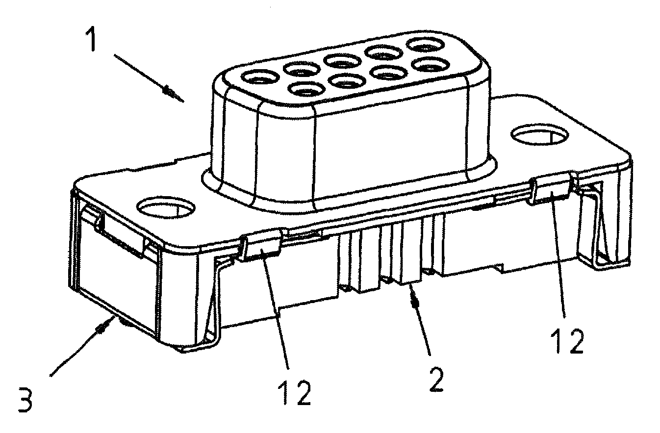
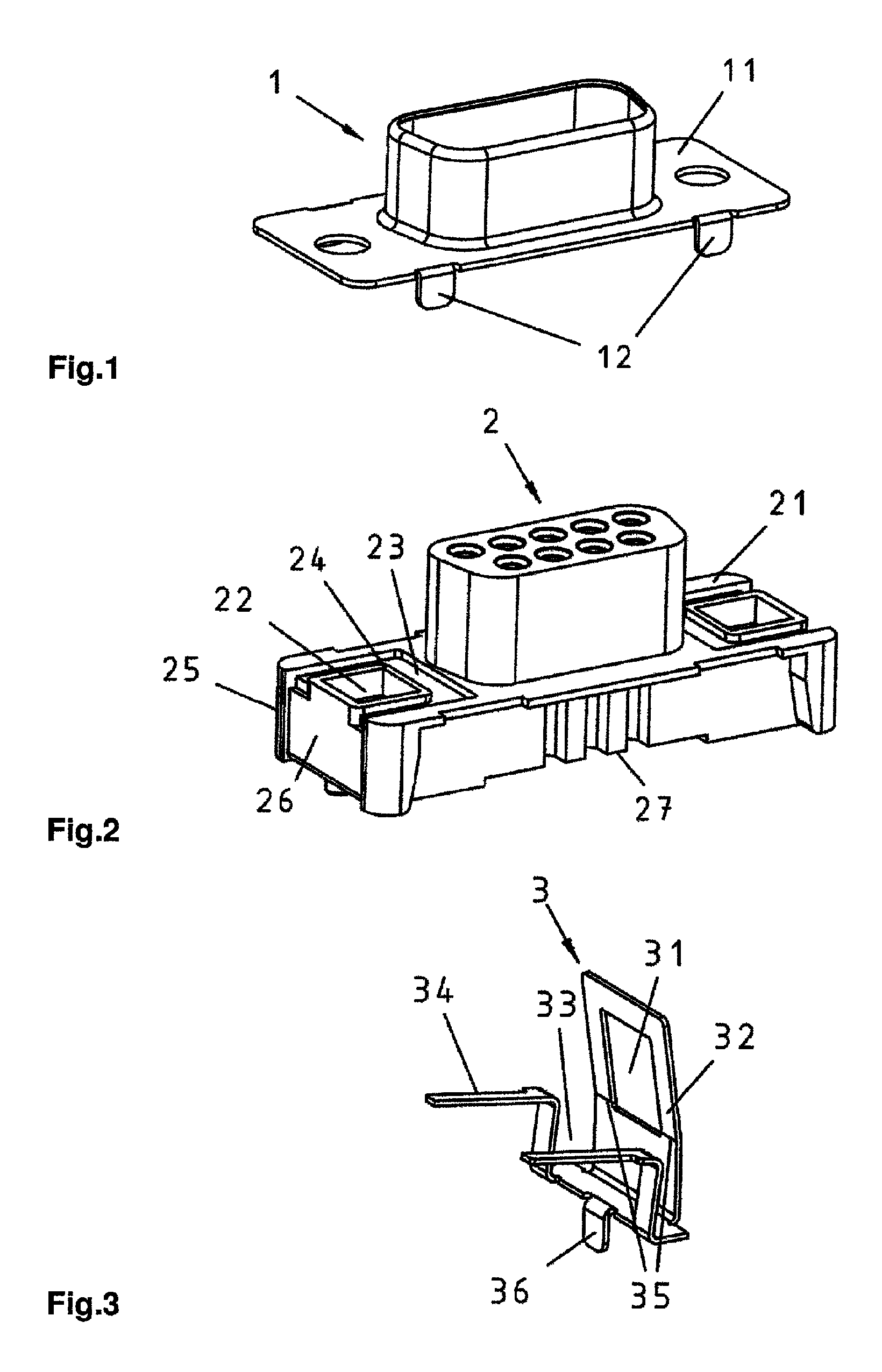
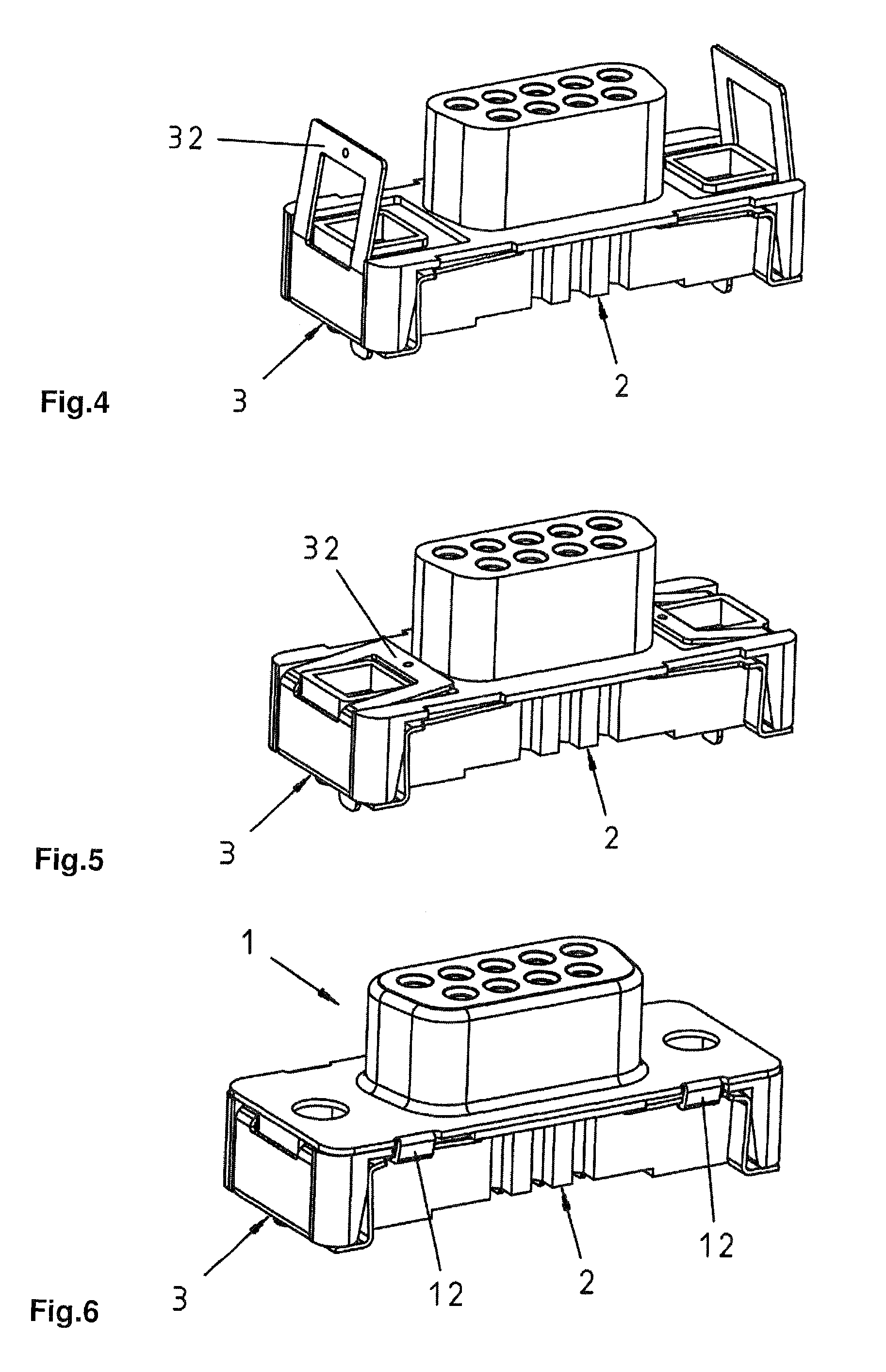
[0027]A D-Sub connector comprises a shielding element 1 that is illustrated in FIG. 1, a base body 2 that is illustrated in FIG. 2 and two lateral fastening elements 3 that are illustrated individually in FIG. 3.

[0028]The shielding element 1 illustrated in FIG. 1 features a peripheral flange 11 with integral tabs 12.

[0029]The base body 2 illustrated in FIG. 2 is manufactured by means of an injection-moulding process and serves as a carrier for electric contacts, wherein this base body consists of an electrically insulating material. The base body 2 features a mounting surface 21, as well as two openings 22 that end in this mounting surface. A recess 23 with an inner collar 24 is respectively arranged in the mounting surface 21 around each of these openings 22. In addition, the base body 2 respectively features an additional recess 26 on two end faces 25. These two additional recesses 26 are provided for fitting the two fastening elements 3 in a gapless fashion.

[0030]The fastening el...


PUM


Abstract

In order to simplify the assembly of a shielded connector, it is proposed that an electrically insulating base body provided as a carrier for electric contacts features a mounting surface with two openings, wherein a recess that respectively features an integral collar on its inner side is respectively arranged around these openings.In addition, the base body is provided with lateral fastening elements that respectively feature a window formed by a frame. The frame can be positively fitted into the appropriate recess by bending the fastening elements such that the fastening element is positively and non-positively fixed on the base body.An electrically conductive shielding element that largely surrounds the base body contacts the fastening elements that, in turn, contact ground strips on the circuit board such that the connector is shielded from external voltages.

Description

BACKGROUND OF THE INVENTION[0001]1. Field of the Invention[0002]The invention pertains to a shielded connector, particularly a D-Sub connector, comprising an electrically insulating base body that serves as a carrier for electric contacts, a metallic shielding element with a peripheral flange and two electrically conductive lateral fastening elements, wherein the base body features a mounting surface, as well as two openings that end in this mounting surface and extend through the base body.[0003]Connectors of this type are mounted on circuit boards and serve for the electrically shielded transmission of electric signals.[0004]2. Description of the Related Art[0005]DE 20 2006 015 908 U1 describes a D-Sub connector with a base element, a shielding element, at least one lateral element and at least one mounting element. The mounting element serves for fastening the connector on a housing and / or for fastening a corresponding connector. The lateral element features at least one fixing e...

Claims


Application Information

Patent Timeline
Patent Type & Authority Patents(United States)
IPC IPC(8): H01R13/648H01R13/658
CPCH01R13/65802H01R4/16H01R13/50H01R12/707H01R13/6582H01R13/658
Inventor VANSSAY, JEAN-MERRI DEDOLLEY, EMMANUELDAUCHELLE, BERTRAND
Owner HARTING ELECTRIC GMBH & CO KG
Why Eureka
Try Eureka