
Real-time code preview for a model based development process

a model-based development and real-time code technology, applied in the field of graphical modeling environment, can solve the problems of large time consumption of model code generation, inability to immediately see the effect of the settings on the code generated for the model, and changes in the exact number and types of function arguments

Inactive Publication Date: 2010-12-07
THE MATHWORKS INC
View PDF28 Cites 90 Cited by
  • Summary
  • Abstract
  • Description
  • Claims
  • Application Information

AI Technical Summary

Benefits of technology

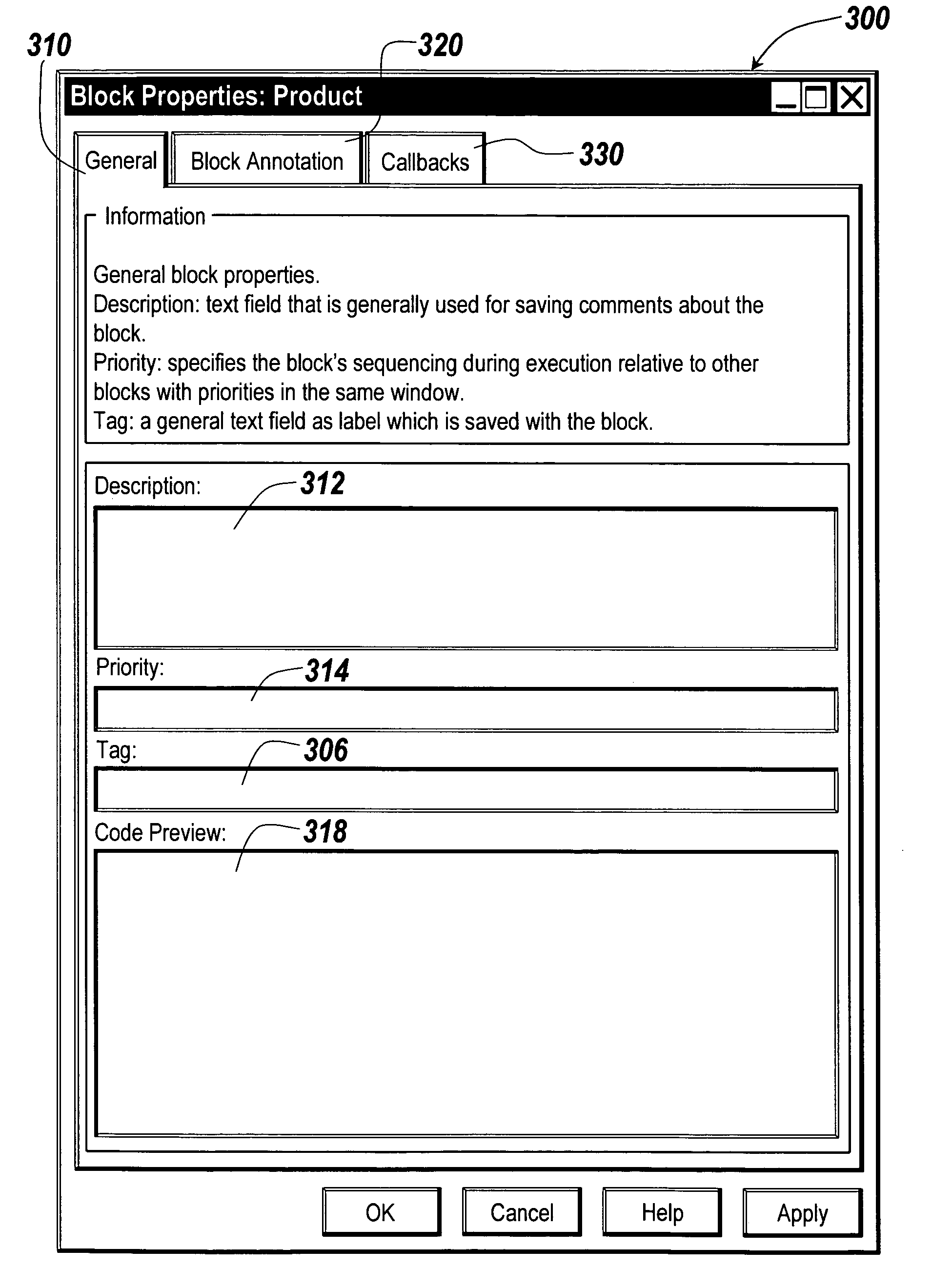
[0009]The present invention provides a preview of aspects of the code generated in response to component and object settings chosen by the user for a graphical model in a graphical modeling environment. The code preview generated in response to a selected component or object in a graphical model is presented using a graphical user interface. The code preview provides feedback to a user regarding the impact of the settings for the

Problems solved by technology

A drawback to current systems is that the affect of the settings on the code generated for the model is not immediately obvious to the users from the model.
Another drawback in current environments is that it can be cumbersome to maintain a literal specification of the function signatures as elements of the model are added and deleted, which changes the exact number and types of function arguments.
In addition, generation of code for a model can consume significant time, and it is not always possible to generate code for a partially specified model.
Such a process is time-consuming, inefficient and at times impossible.

Method used


Image

  • Real-time code preview for a model based development process
  • Real-time code preview for a model based development process
  • Real-time code preview for a model based development process

Examples


Embodiment Construction

[0027]An illustrative embodiment of the present invention relates to a user interface for specifying parameters of an object or component in a model within a model in a graphical modeling environment. A user interface further provides a real time code preview of aspects of code generated in response to the object and / or component settings selected by the user. The user interface that provides the code preview may be the same interface used to select the parameters of the object and / or component. The present invention will be described relative to illustrative embodiments. Those skilled in the art will appreciate that the present invention may be implemented in a number of different applications and embodiments and is not specifically limited in its application to the particular embodiments depicted herein.

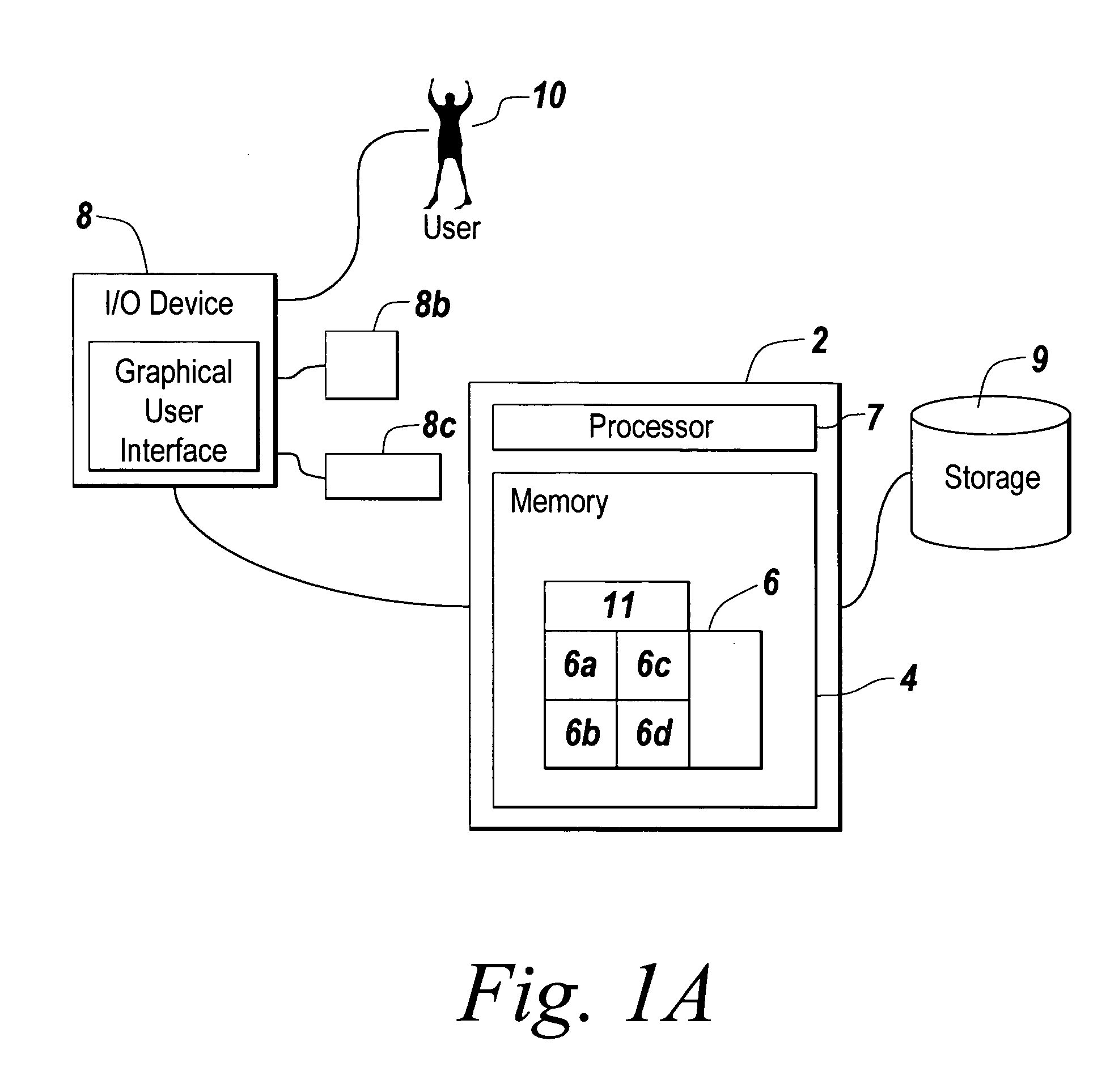
[0028]FIG. 1A depicts an environment suitable for practicing an illustrative embodiment of the present invention. An electronic device 2 includes memory 4, on which software accord...


PUM


Abstract

In a graphical modeling environment, a preview of code generated in response to a selected component in a graphical model is presented using a graphical user interface. The code preview provides feedback to a user regarding the impact of the settings for the selected component, allowing the user to observe the effect of certain settings before generating code for the entire graphical model. The code preview may be presented through the same graphical user interface used to select the settings for the component, or a separate graphical user interface.

Description

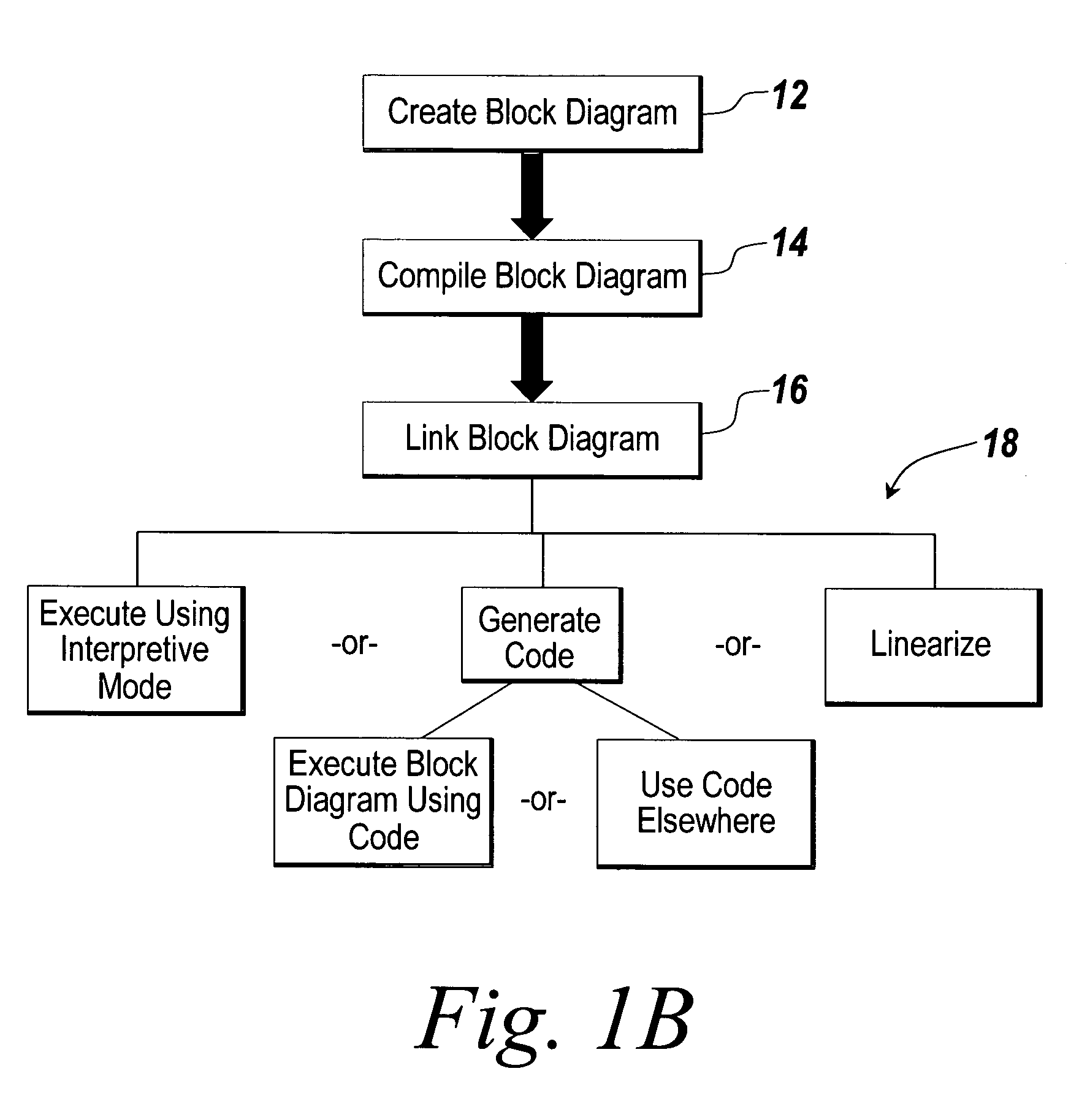
FIELD OF THE INVENTION[0001]The present invention relates to a graphical modeling environment for modeling a dynamic system. More particularly, the present invention relates to code generation in a graphical modeling application.BACKGROUND OF THE INVENTION[0002]Many organizations are embracing the paradigm of Model Based Development in their production processes. “Model Based Development” refers to the practice of specifying, analyzing, and implementing systems using a common “model” consisting of a set of block diagrams and associated objects. System implementation typically consists of automatically generating code for portions of the model, particularly portions corresponding to the system's control algorithm.[0003]Graphical modeling environments are an example of software applications that may enable a user to model, simulate, and analyze dynamic systems i.e., systems whose outputs change over time, using a graphical model, such as a block diagram. Simulating a dynamic system in...

Claims


Application Information

Patent Timeline
IPC IPC(8): G06F9/44G06F3/00G06F3/048
CPCG06F8/34G06F9/45504
Inventor ENGLEHART, MATTHEW
Owner THE MATHWORKS INC
Learn More