Collapsible stand for machine

a technology for supporting a machine and a platform, which is applied in the direction of folding cycles, carriers/perambulators with multiple axes, manufacturing tools, etc., can solve the problems of complicated and inconvenient operation, increased risk for users, and difficulty in turning and then folding the stand b>80/b>, so as to facilitate the spread of open or fold, smoothly and stably lower the platform and the machine supported on the platform, and lift the platform and the machin

Inactive Publication Date: 2010-12-14
REXON IND CORP LTD
View PDF42 Cites 13 Cited by
  • Summary
  • Abstract
  • Description
  • Claims
  • Application Information

AI Technical Summary

Benefits of technology

[0007]The present invention has been accomplished in view of the circumstances discussed above. It is therefore one objective of the present invention to provide a collapsible stand that can be conveniently and easily spread open for use and folded for carrying and / or storage.
[0009]By means of the locking means, the two second legs can be conveniently locked relative to the platform after the stand is spread open and released from the locked position when the user wants to fold the stand. By means of the assembly of the locking means, the two sleeves and the two pairs of the first leg and the interconnected second leg, the user can easily spread open or fold the collapsible stand without turning it over. Further, when the user folds the stand, the springy or biasing member provides a damping resistance to the platform to help the user smoothly and stably lower the platform and the machine supported on the platform. Furthermore, when the stand is spread open, the springy or biasing member provides a rebound force to the platform, thereby enabling the user to lift the platform and the machine with less effort. In a preferred embodiment of the present invention, the springy or biasing member is a spring so as to reduce the manufacturing cost of the stand. In addition, after the stand is spread open, the stand is steadily supported on the floor by the stable structure thereof. Thereby, the present invention improves upon the disadvantages of the prior stands.

Problems solved by technology

In this manner, turning and then folding the stand 80, is complicated and inconvenient.
Moreover, the operation is not easy for the user and the user is further in danger when turning the table saw 82 and the platform 81 from the horizontal to the vertical by himself because of the heavy weight of table saw 82 and the stand 80.
However, it is expensive to use the gas spring 91 and the piston rod 92 to produce a damping resistance.
However, the rotatable connection between the wheels 94 and the bottom ends of two legs 93 is not stable.

Method used


Image

  • Collapsible stand for machine
  • Collapsible stand for machine
  • Collapsible stand for machine

Examples


Embodiment Construction

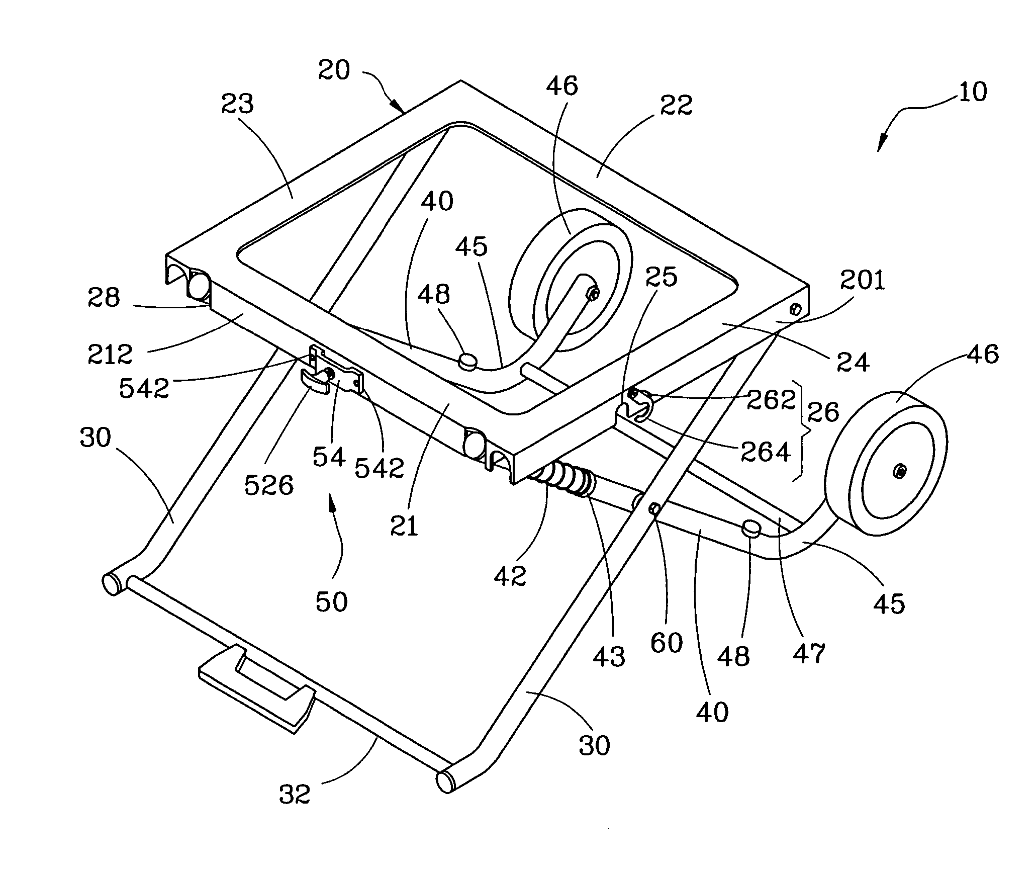
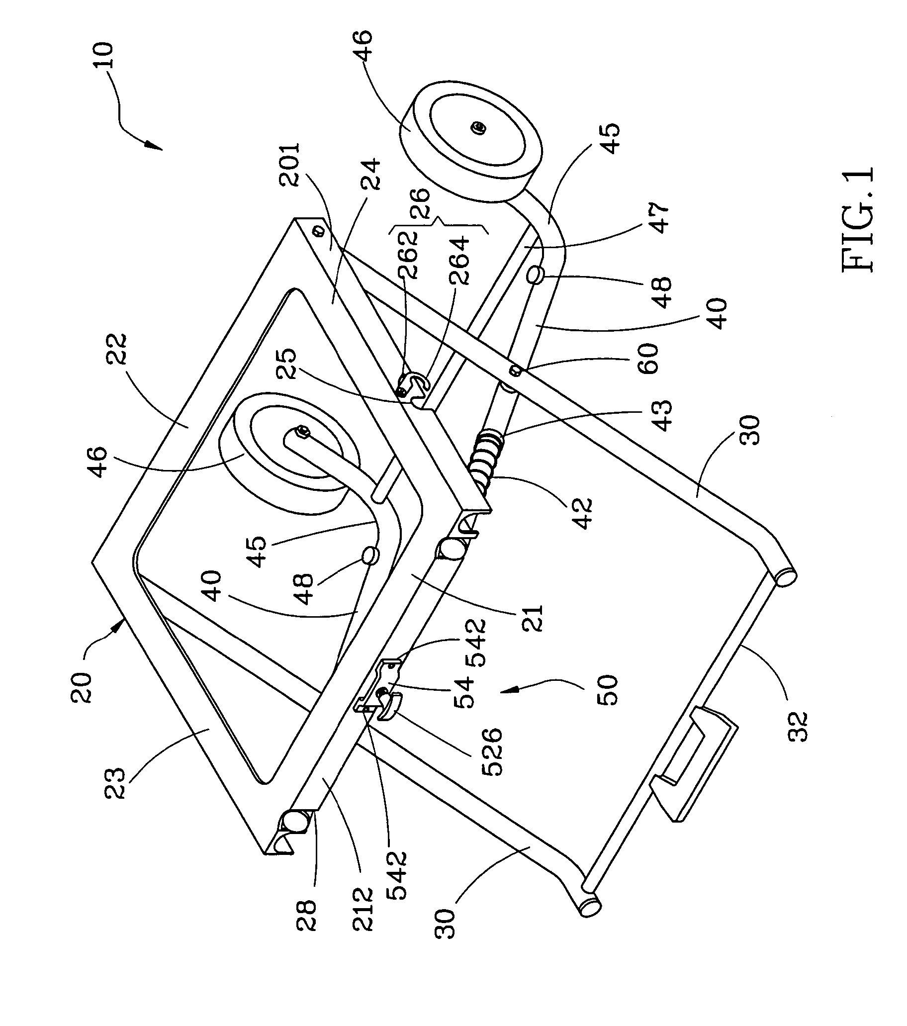
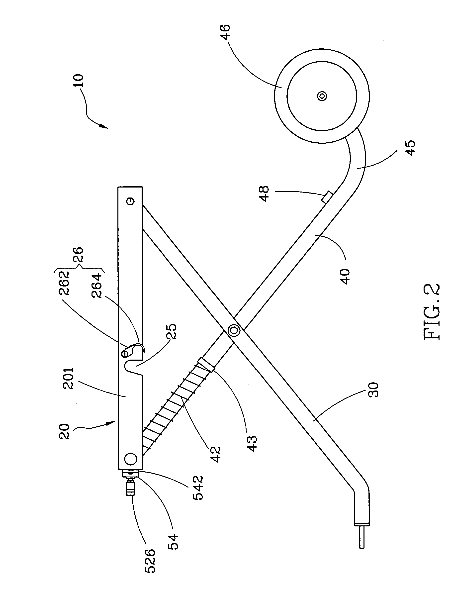
[0022]As shown in FIGS. 1 and 2, a collapsible stand 10 in accordance with a first preferred embodiment of the present invention has a platform 20, two first legs 30, two second legs 40, two first springy or biasing members 42, and a locking device 50.

[0023]The platform 20 is adapted to carry a machine (not shown), such as a wood working machine (e.g., table saw, miter saw, scroll saw, band saw, drill press, sander, etc.). The platform 20 can be a plate or a frame. According to this embodiment, the platform 20 is a rectangular frame, having a front frame part 21, a rear frame part 22, a left frame part 23, and a right frame part 24. An outside wall 201 of each of the left frame part 23 and the right frame part 24 has an arched notch 25. Two swivel hooks 26 are respectively pivotally mounted to the outside walls 201 of the left frame part 23 and the right frame part 24 adjacent to the arched notches 25. Each of the swivel hooks 26 has a hooked portion 264 pivotally connected to the o...


PUM


Abstract

A collapsible stand includes a platform for supporting a machine, two first legs each having a top end pivotally connected to the platform, two second legs each of which is pivotally connected to each first leg and has a top part slidably inserted through a sleeve of the platform, at least one springy or biasing member and a locking device. The springy or biasing member is retained in a sleeve-like or coaxial manner on retained in a sleeve-like manner one of the second legs. The locking device is connected to the platform for fixing the second legs in position after spreading the stand open such that the first legs and second legs support the platform at a predetermined height.

Description

BACKGROUND[0001]1. Field of the Invention[0002]The present invention relates to a collapsible stand for supporting a machine, and more particularly the collapsible stand can easily and conveniently be spread open for use and folded for carrying and / or storage.[0003]2. Description of the Related Art[0004]U.S. Pat. No. 6,942,229B2, discloses a collapsible stand for a bench-top power tool. In the patent, as shown in FIGS. 10 and 11, the stand 80 includes a platform 81 on which a table saw 82 is mounted, two first legs 83 are pivotally connected to the bottom side of the platform 81, two second legs 84 are respectively connected to the two first legs 83 in a crossed manner, and two wheels 85 are bilaterally connected to the front part of the platform 81. When wanting to move the table saw 82, the user must turn the table saw 82 and the platform 81 from a horizontal position to a vertical position in order to place the front side of the table saw in contact with the floor, and then fold ...

Claims


Application Information

Patent Timeline
Patent Type & Authority Patents(United States)
IPC IPC(8): B62B3/02
CPCB25H1/04
Inventor CHIU, CHENG-HUNG
Owner REXON IND CORP LTD
Why Eureka
Try Eureka