
Method and device for clamping of crushing shell

a technology of clamping shell and crushing shell, which is applied in the direction of metal-working equipment, metal-working equipment, manufacturing tools, etc., can solve the problems of mechanical complexity of the locking device disclosed in u.s. pat. no. 6, 007, 009

Inactive Publication Date: 2010-12-14
SANDVIK INTELLECTUAL PROPERTY AB
View PDF8 Cites 4 Cited by
  • Summary
  • Abstract
  • Description
  • Claims
  • Application Information

AI Technical Summary

Benefits of technology

The present invention provides a method for securely fixing an outer shell in a gyratory crusher. The method involves first abutting the outer shell against a frame and then using a spacer member to clamp the outer shell inwardly against the frame. This method provides a flexible and robust fixing of the outer shell, with good abutment surfaces that can withstand the crushing forces. The invention also provides an outer shell that is easy to manufacture and withstands mechanical load during crushing. The technical effects of the invention are improved stability and flexibility of the outer shell in the crusher.

Problems solved by technology

The locking devices disclosed in U.S. Pat. No. 6,007,009 are, however, mechanically complicated and involve a mechanically seen weak fixing of the outer shell.

Method used


Image

  • Method and device for clamping of crushing shell
  • Method and device for clamping of crushing shell
  • Method and device for clamping of crushing shell

Examples


Embodiment Construction

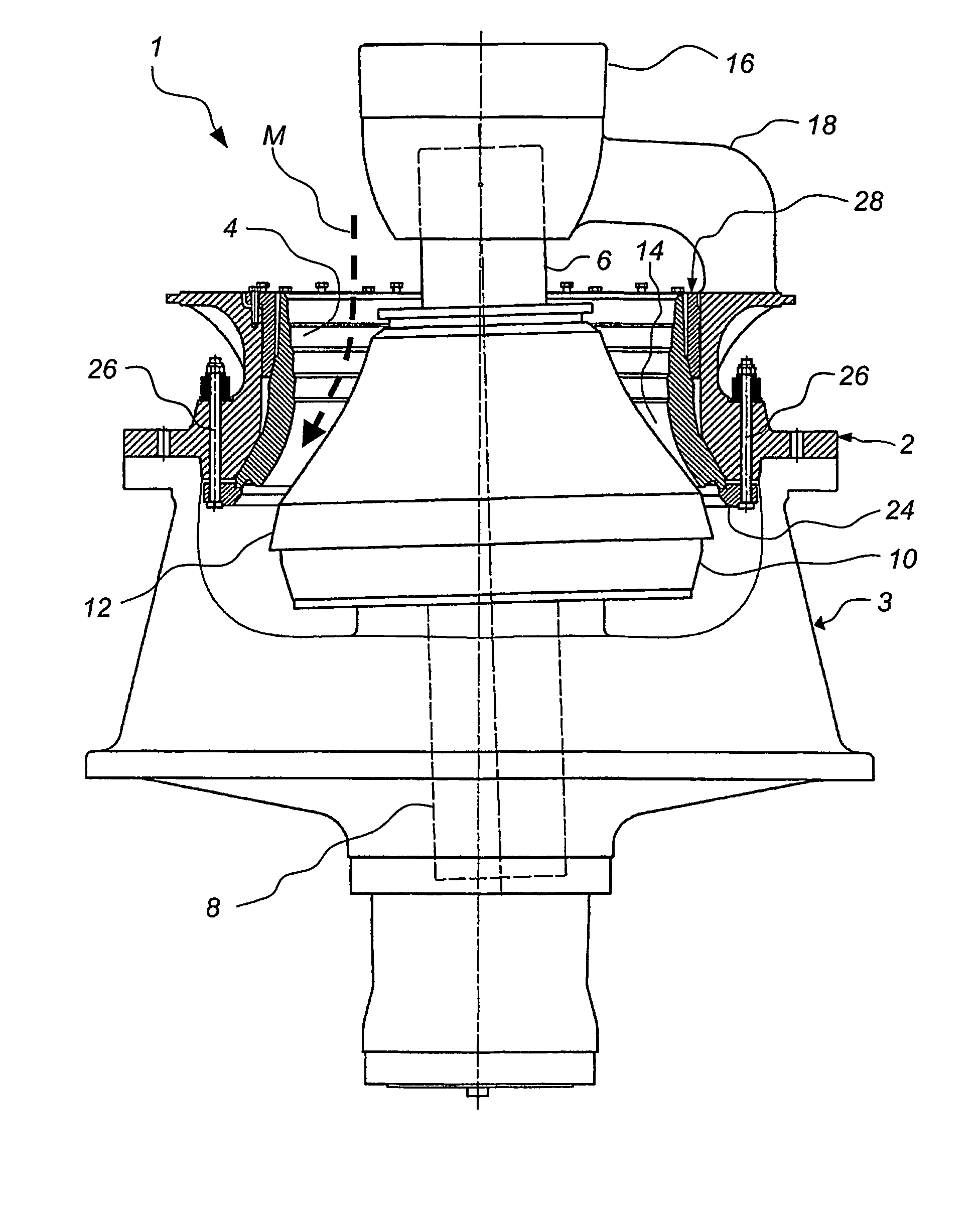
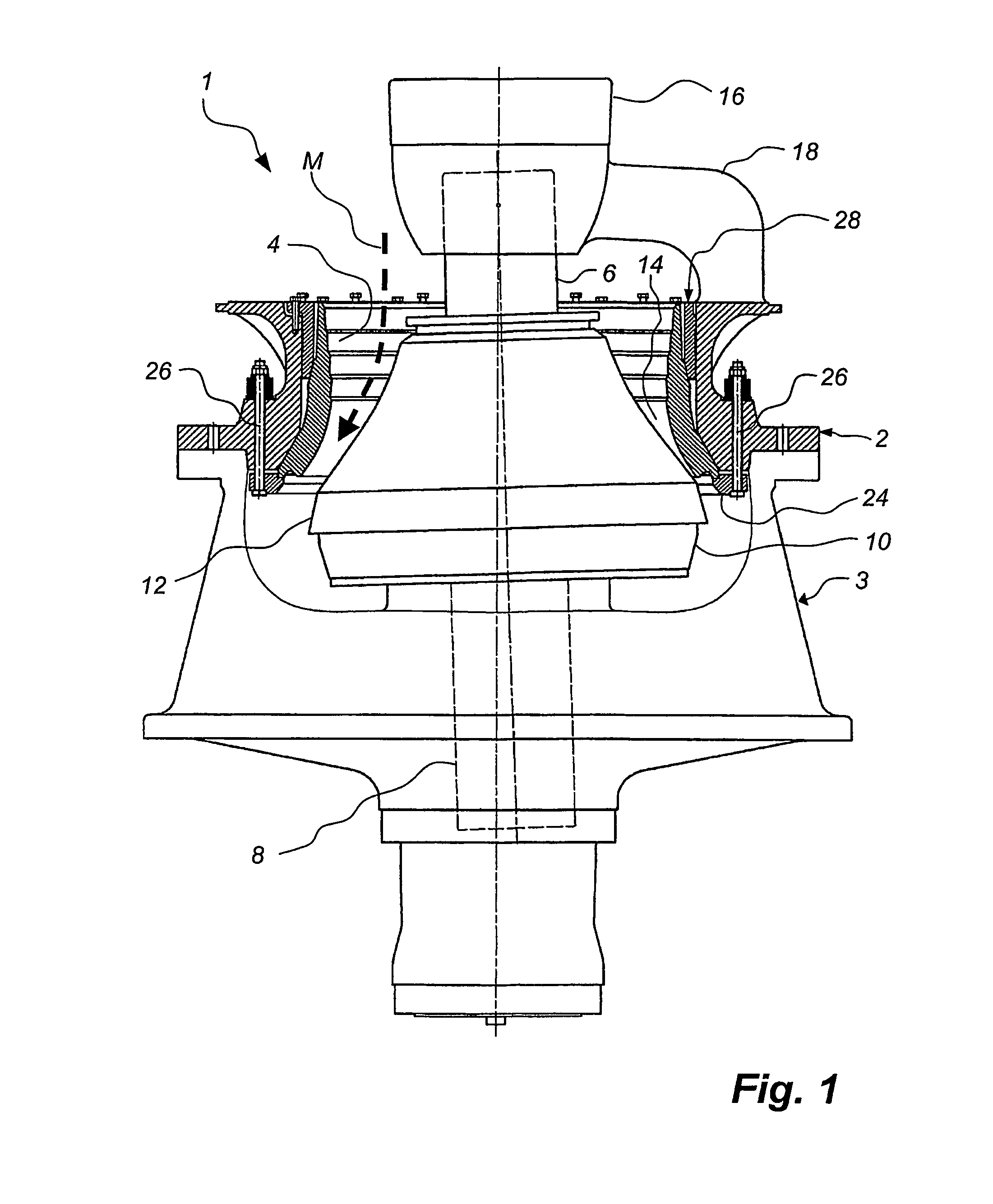
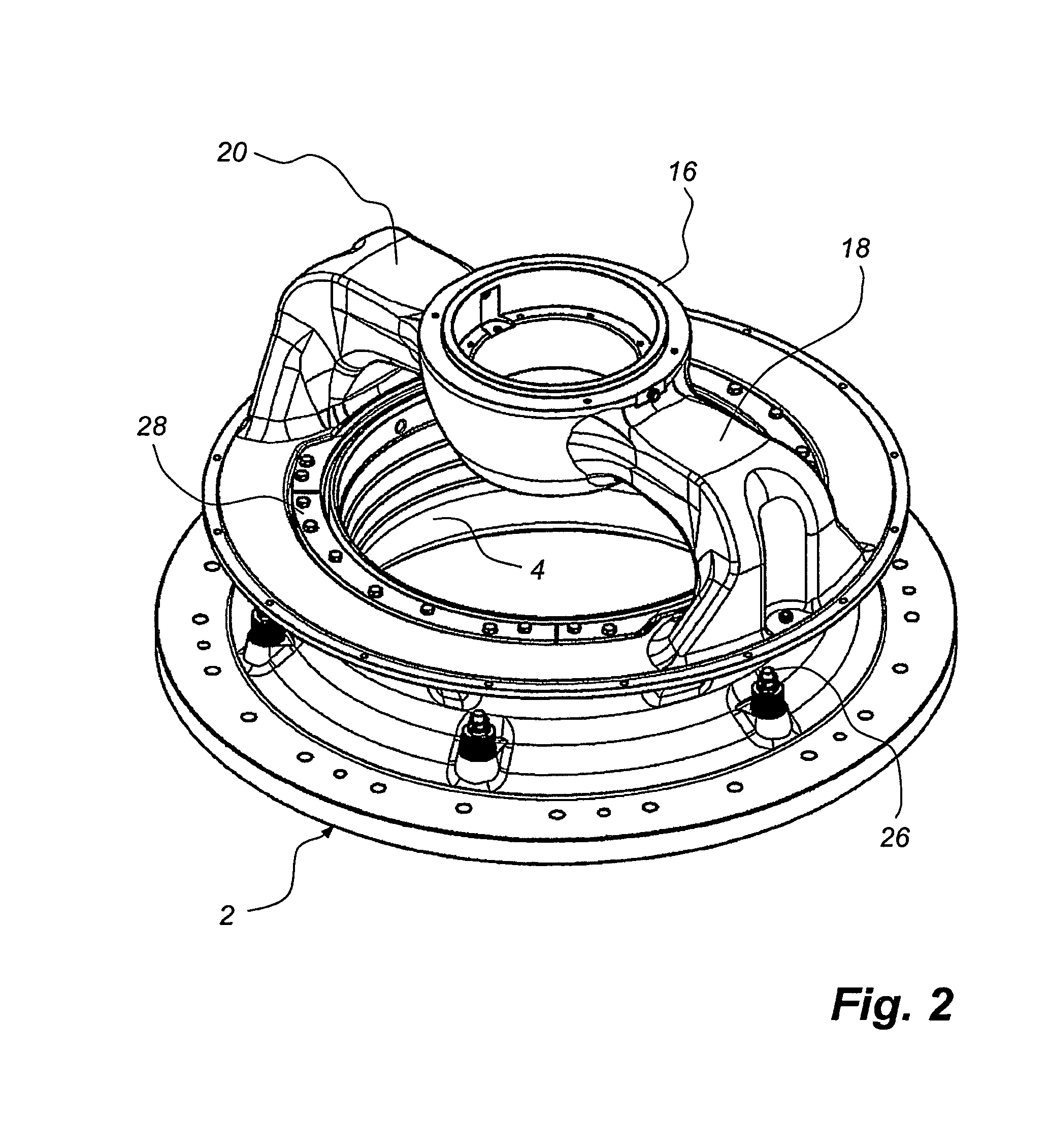
[0047]In FIG. 1, a gyratory crusher 1 is shown schematically, which has a frame in the form of an upper part 2, which is detachably attached on a bottom part 3. In the upper part 2, a crushing shell in the form of an outer shell 4 is attached. The outer shell 4 is of a type, which is utilized in crushing of relatively rough material. The gyratory crusher 1 has also a shaft 6. At the lower end 8 thereof, the shaft 6 is eccentrically mounted in the bottom part 3. At the upper end thereof, the shaft 6 carries a crushing head 10. A second crushing shell in the form of an inner shell 12 is mounted on the outside of the crushing head 10. The outer shell 4 surrounds the inner shell 12 in such a way that between said shells 4, 12, a crushing gap 14 is formed, which in axial section, such as is shown in FIG. 1, has in direction downwardly decreasing width. The shaft 6, and thereby the crushing head 10 and the inner shell 12, is vertically movable by means of a hydraulic adjusting device, not...


PUM

PropertyMeasurementUnit
angleaaaaaaaaaa
angleaaaaaaaaaa
angleaaaaaaaaaa

Abstract

A gyratory crusher includes an outer shell, which should be fastened in a frame included in the crusher, and an inner shell, which is intended to be fastened on a crushing head and to define together with the outer shell a crushing gap for receipt of material to be crushed. Upon fastening of the outer shell a first abutment surface on the outer periphery of the outer shell is brought in a first step to abutment against a first contact surface on the frame. In a second step a spacer member is pressed in for clamping of the outer shell between a second surface on the outer periphery of the outer shell and the frame. A good abutment is provided both at the first abutment. Surface of the outer shell and at the second abutment surface thereof.

Description

TECHNICAL AREA[0001]The present invention relates to a method to fasten an outer shell in a gyratory crusher, which comprises the outer shell, which is to be fastened in a frame included in the crusher, and an inner shell, which is intended to be fastened on a crushing head and together with the outer shell define a crushing gap for receipt of material which is to be crushed.[0002]The present invention also relates to an outer shell for fixing in a gyratory crusher.[0003]The invention also relates to a gyratory crusher, which is of the above-mentioned kind and in which an outer shell can be fixed.[0004]The invention also relates to a spacer member for use in the fixing of an outer shell in a gyratory crusher.TECHNICAL BACKGROUND[0005]A gyratory crusher, which is of the above-mentioned kind, can be utilized for crushing hard objects, for instance blocks of stone. During the crushing, the shells of the crusher are worn and these therefore have to be exchanged at regular intervals. Ano...

Claims


Application Information

Patent Timeline
Patent Type & Authority Patents(United States)
IPC IPC(8): B02C2/00B02CB02C2/06
CPCB02C2/005Y10T29/53
Inventor OLSSON, GERT-.ANG.KESILFVER, ROLFWULFF, TORBJORN NILSSON
Owner SANDVIK INTELLECTUAL PROPERTY AB
Learn More