Connecting device for spinal osteosynthesis

a technology of connecting device and spinal cord, applied in the field of spinal cord osteosynthesis, can solve the problems of inability to tilt stabilize the rod, prior art devices suffer from drawbacks, and the movement allowed on the bone screw remains relatively small, and achieves the effect of increasing the exten

Active Publication Date: 2010-12-14
SPINEVISION
View PDF20 Cites 70 Cited by
  • Summary
  • Abstract
  • Description
  • Claims
  • Application Information

AI Technical Summary

Benefits of technology

[0010]An object of the present invention is to remedy the drawbacks of the prior art by proposing a connector device that makes it possible to increase the extent to which the connector holding the coupling rod can move on the anchor means used on the vertebrae.
[0011]An object of the present invention is thus to provide a device that makes manipulation easy, and more particularly that facilitates assembling the coupling rod to the anchor means and disassembling said coupling rod therefrom, and that facilitates unscrewing the anchor means during readjustment surgery.

Problems solved by technology

The problem that arises with that solution is that the rod is not tilt-stabilized in a plane containing the coupling rod and passing through the bone screw.
Unfortunately, the prior art devices suffer from drawbacks.
Firstly, the movements that are allowed on the bone screws remain relatively small, in particular in the frontal plane.
This then results in manipulation difficulties, and in particular difficulties in assembling the coupling rods to the bone screws and in disassembling them therefrom.
Secondly, during re-adjustment surgery, it can be difficult to unscrew the bone screw due to the drive means of the screw not being aligned with the head that receives the coupling rod.

Method used


Image

  • Connecting device for spinal osteosynthesis
  • Connecting device for spinal osteosynthesis
  • Connecting device for spinal osteosynthesis

Examples


Embodiment Construction

)

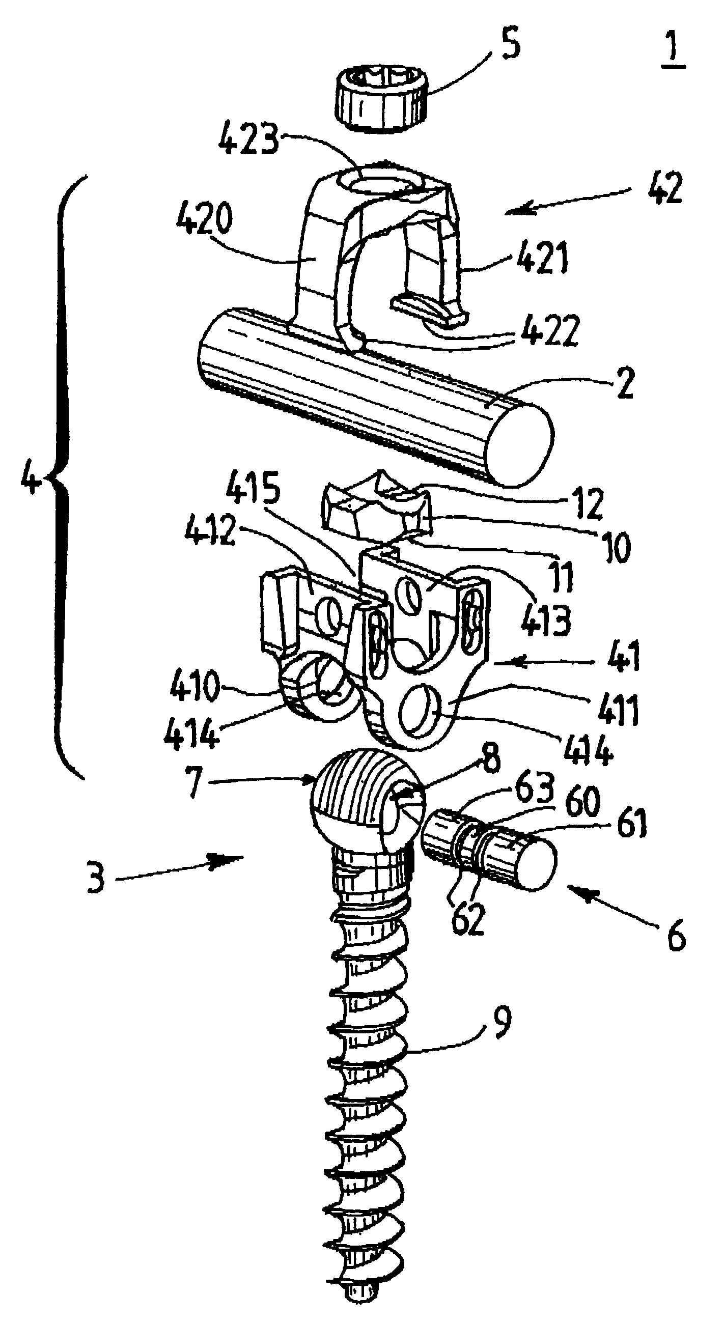
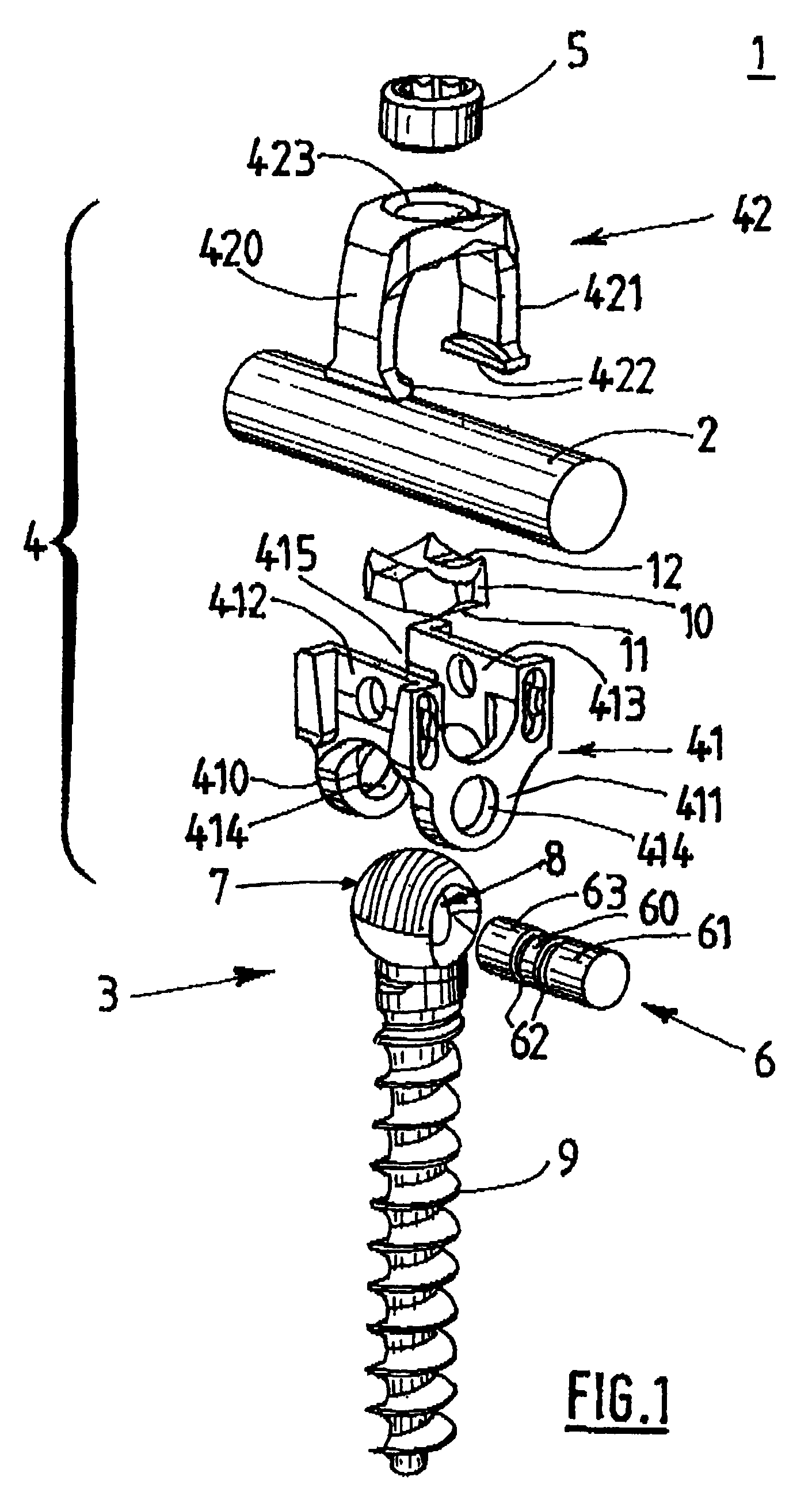
[0044]FIG. 1 is an exploded view of a connector device (1) of the invention for spinal osteosynthesis. Said connector device (1) is shown with a vertebrae coupling rod (2).

[0045]Said connector device (1) comprises bone anchor means (3) and a connector (4) for connection to a coupling rod (2). Said device (1) further comprises tightening means (5) for immobilizing the anchor means (3) and the connector (4) holding the coupling rod (2).

[0046]Advantageously, said bone anchor means (3) consists of a bone screw (3) made up of a threaded portion (9) and, at one of its ends, of a spherical head (7). The head (7) of said screw (3) is provided with a cavity (8) designed to be passed through a cylindrical pin (6). The coupling between the cavity (8) and the pin (6) is achieved in a manner such as to allow said pin (6) to turn in said cavity (8). For this purpose, the person skilled in the art can, in particular, act on the dimensions of the cavity (8) formed in the head (7) of the screw (3) ...


PUM


Abstract

A connecting device for spinal osteosynthesis has an osseous anchoring device, a connector that accommodates a joining shaft and is fixed to one end of the anchoring device, and a tightening device for immobilizing the joining shaft. The connecting device is characterized in that the connector is fixed to the anchoring device with the aid of a pin that penetrates the anchoring device and embodies a pivot joint. Furthermore, the device comprises an arrangement for stabilizing the connector relative to the anchoring device when the device is implanted in the patient, the stabilizing arrangement being located on the plane encompassing the shaft and the anchoring device.

Description

BACKGROUND OF THE INVENTION[0001](1) Field of the Invention[0002]The present invention relates to the field of spinal osteosynthesis serving in spine surgery for correcting and stabilizing the spinal column.[0003]The present invention relates more particularly to a connector device for spinal osteosynthesis, said connector device comprising osseous anchor means, a connector designed to receive a coupling rod and assembled to one end of the anchor means, and tightening means for immobilizing the coupling rod.[0004](2) Prior Art[0005]Numerous systems are known in the prior art for correcting or stabilizing the spinal column.[0006]German Utility Model DE 41 07 480 describes a bone screw designed to fasten a device for correcting and stabilizing the spinal column. For that purpose, that bone screw has a head provided with a semicircular recess zone for receiving the coupling rod. Said coupling rod is locked onto the head of the bone screw by a substantially U-shaped closure piece, said ...

Claims


Application Information

Patent Timeline
Patent Type & Authority Patents(United States)
IPC IPC(8): A61B17/70
CPCA61B17/7037A61B17/7038A61B17/7032A61B17/70
Inventor BETTE, STEPHANEPETIT, DOMINIQUETHIBOUT, DIDIERVANACKER, GERARD
Owner SPINEVISION
Why Eureka
Try Eureka