Image display apparatus with hydrophobic diffraction grating for an enlarged viewing angle

a technology of hydrophobic diffraction grating and image display apparatus, which is applied in the direction of optical viewing, vehicle components, instruments, etc., can solve the problems of deteriorating image quality, insufficient image quality of conventional image display devices, and difficulty for a number of persons to view one display face of image display apparatus at the same tim

Inactive Publication Date: 2000-05-23
KURARAY CO LTD
View PDF11 Cites 58 Cited by
  • Summary
  • Abstract
  • Description
  • Claims
  • Application Information

AI Technical Summary

Problems solved by technology

Accordingly, it is difficult for a number of persons to view one display face of the image display apparatus at the same time.
Further, when a large screen of the image display apparatus is viewed in close proximity, there is recognized the difference of contrast between the central portion and the peripheral portion of the display face whereby the image quality is deteriorated.
The above-mentioned problem is particularly significant in an image display apparatus using a liquid crystal panel as an image display device.
However, sufficient image quality has not been achieved in these conventional image di

Method used


Image

  • Image display apparatus with hydrophobic diffraction grating for an enlarged viewing angle
  • Image display apparatus with hydrophobic diffraction grating for an enlarged viewing angle
  • Image display apparatus with hydrophobic diffraction grating for an enlarged viewing angle

Examples


first embodiment

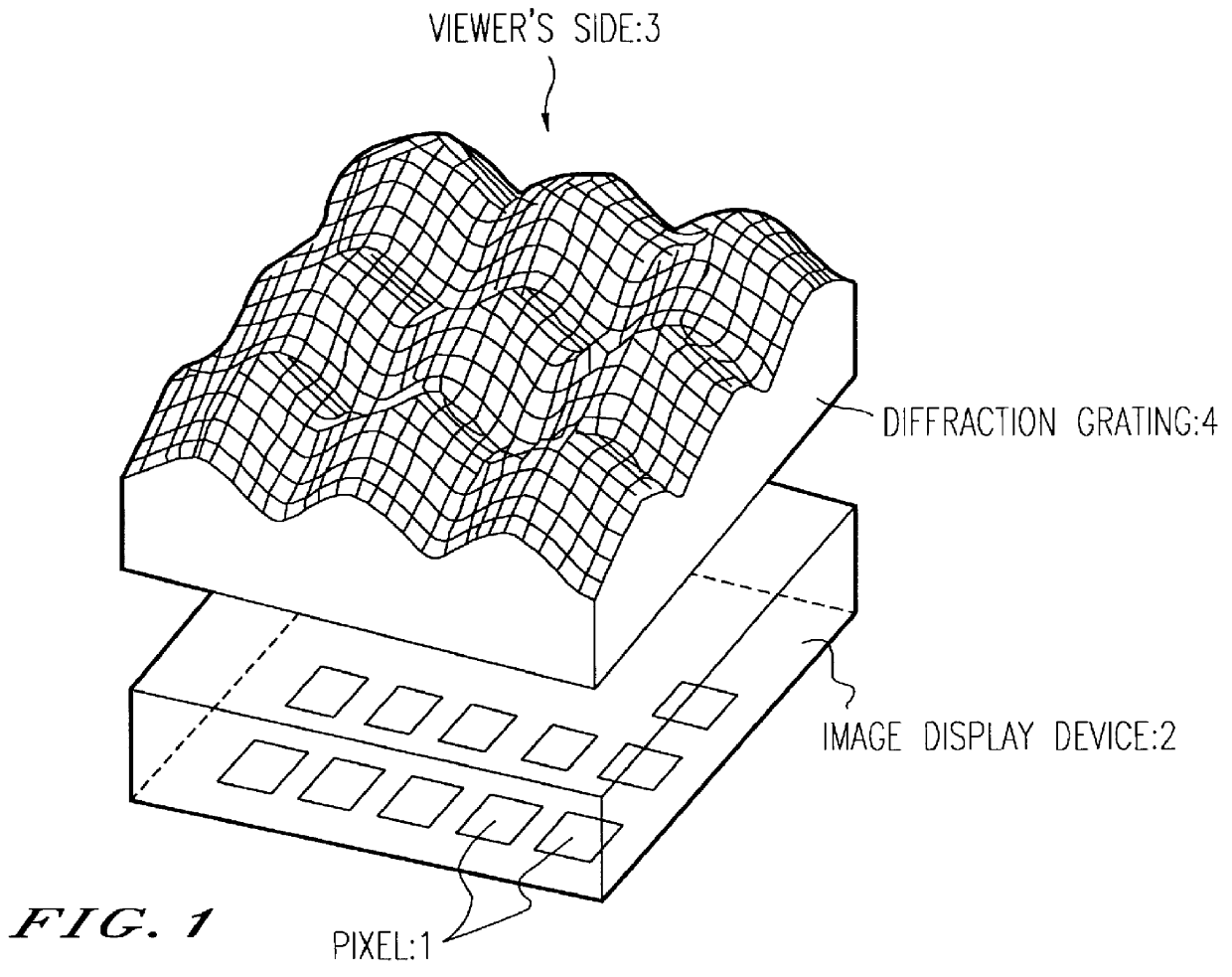
FIG. 1 illustrates the outline structure of an image display apparatus according to the present invention. The image display apparatus is provided with an image display device 2 in which pixels 1 are arranged in a dot-like form and a diffraction grating 4 having a lattice face. The diffraction grating 4 is arranged on a display optical path of the image display device 2 such that the lattice face of the diffraction grating 4 faces toward a viewer's side 3. The pixels 1 of the image display device control light emitted by the pixels per se, light incident on the pixels from a light source provided on the side opposed to the viewer's side or light incident on the pixels from a light source provided on the viewer's side and the image display device 2 displays an image by controlling the pixels. The diffraction grating in the image display apparatus as illustrated in FIG. 1 is provided with a sectional shape in a continuous curve and the sectional shape is substantially in a form of a s...

second embodiment

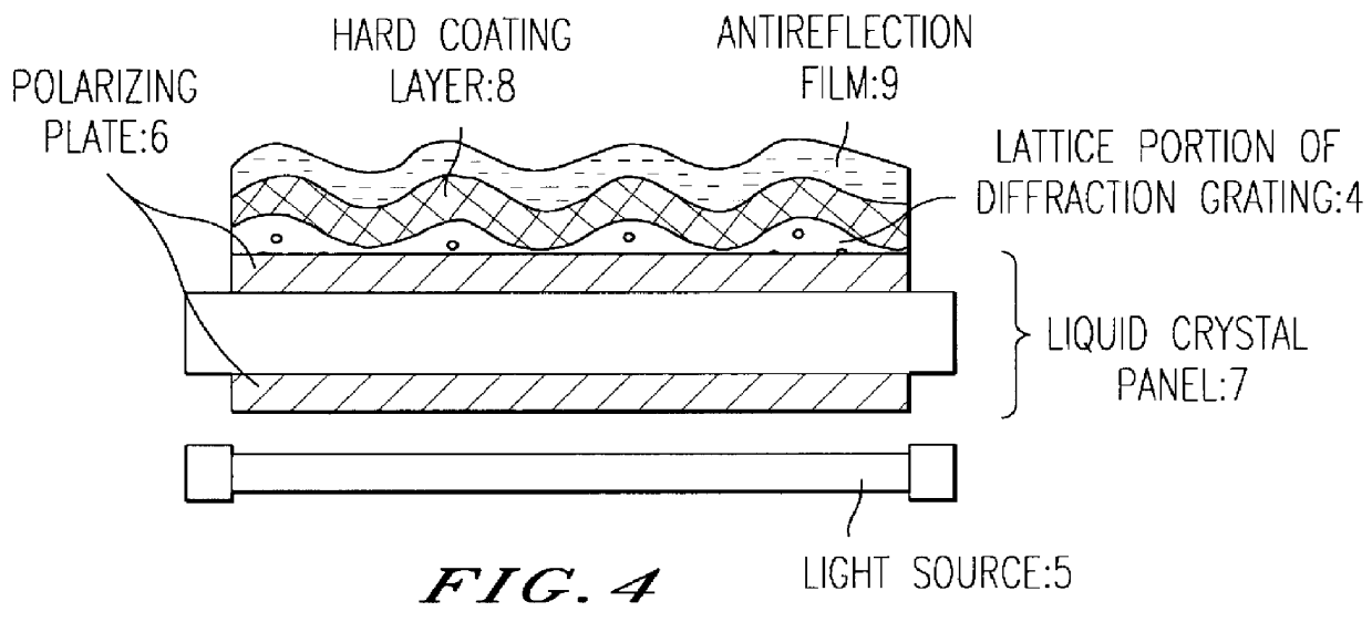
FIG. 4 shows the outline structure of an image display apparatus according to the present invention. According to the image display apparatus a liquid crystal panel 7 of a TFT type is used as an image display device and a lattice portion 4 of a diffraction grating is provided directly on a polarizing plate 6 that is disposed on the side opposed the side of a light source 5. The poly(vinyl alcohol)film is sandwiched by the TAC films in the polarizing plate 6. That is, the TAC film on the viewer's side of the polarizing plate corresponds to the base portion of the diffraction grating. A hard coating layer 8 and an antireflection film 9 are installed from the side of the lattice portion 4 of the diffraction grating, on the viewer's side of the diffraction grating. According to this embodiment of the image display apparatus an apparatus in which the brightness of displayed image is high and the displayed image is difficult to be flawed, is provided. In this image display apparatus there...


PUM


Abstract

An image display apparatus including an image display device in which pixels are arranged in a dot-like form and a diffraction grating having a lattice face with a water contact angle of 70 DEG or more. The diffraction grating is arranged on a display optical path of the image display device such that the lattice face of the diffraction grating faces toward a side of a viewer and a viewing angle of the image display device is enlarged by the diffraction grating.

Description

1. Field of the InventionThe present invention relates to an image display apparatus using an image display device represented by liquid crystal panels.2. Description of Related ArtAn image display apparatus using an image display device in which pixels are arranged in a dot-like form and which is represented by a light emitting diode array, a liquid crystal panel of a TFT (thin film transistor) active matrix type etc., has been developed. According to such an image display apparatus the contrast of an image displayed on the image display apparatus is significantly changed by the magnitude of an angle made by a direction for viewing the image display apparatus and a direction orthogonal to a display face of the image display apparatus (that is, an angle whereby a direction in which a viewer is disposed, in view from the display face of the image display apparatus, is deviated from a direction orthogonal to a frontal face of the image display apparatus) and fair image quality can be ...

Claims


Application Information

Patent Timeline
IPC IPC(8): G02F1/13G02F1/1335
CPCG02F1/133504G02F1/1335
Inventor OHNISHI, IKUOFUJISAWA, KATSUYAWATANABE, RIKUJIHAYASHI, KATSUHIKO
Owner KURARAY CO LTD
Why Eureka
Try Eureka