Infrared touchframe system

a touchframe and infrared technology, applied in the field of touchframe technology, can solve the problems of touch event and touchframe system to provide false readings

Active Publication Date: 2010-12-21
COVIDIEN LP
View PDF6 Cites 312 Cited by
  • Summary
  • Abstract
  • Description
  • Claims
  • Application Information

AI Technical Summary

Problems solved by technology

When a stylus, such as a finger, enters the grid, it obstructs the beams thereby resulting in a touch event.
Ambient light and other optical noise in the touch environment may cause the touchframe system to provide false readings.
For example, noise may cause an IR receiver to provide an output indicative of an unobstructed or connected light beam when the light beam is in fact obstructed or blocked.
A problem with such operation is that infrared light emitted by the sequential, regular pulsing of LEDs may leak into the surrounding environment and inadvertently activate devices which are remotely controllable using infrared remote controls.
This can be a significant problem if the touchframe is on a medical devices, such as a ventilator, and it inadvertently activate other medical devices nearby.

Method used


Image

  • Infrared touchframe system
  • Infrared touchframe system
  • Infrared touchframe system

Examples


Embodiment Construction

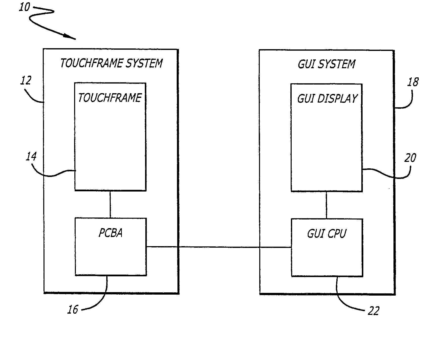
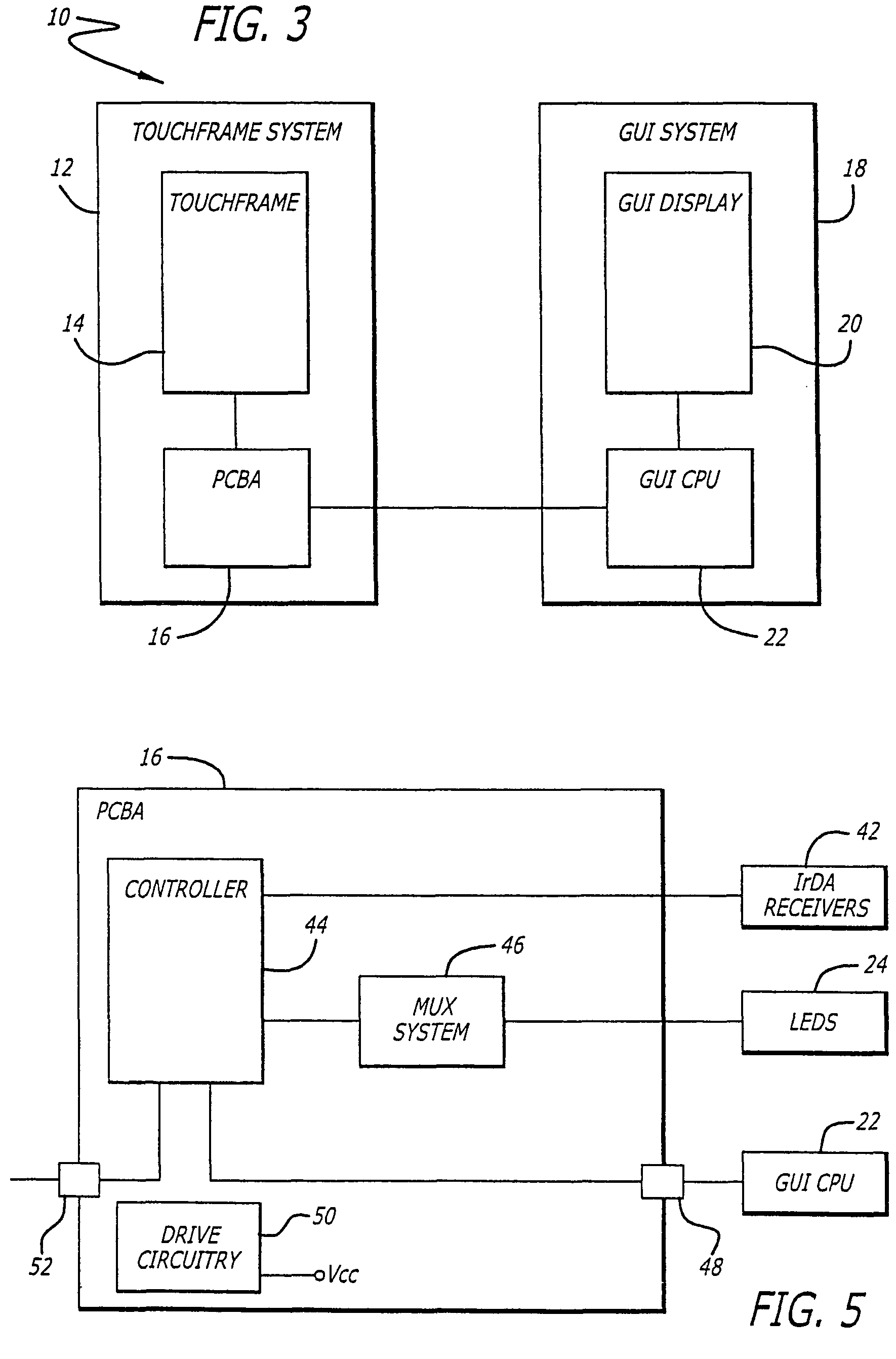
[0035]Referring now to the drawings, which are provided for the purposes of illustration and not by way of limitation, and particularly to FIG. 3, there is shown a system 10 incorporating an infrared touchframe system 12 configured in accordance with the invention and including a touchframe 14 and printed circuit board assembly (PCBA) 16. The system 10 also includes a graphical user interface (GUI) system 18 which includes a GUI display 20 and a GUI central processing unit (CPU) 22. Detailed descriptions of the system architecture and system operation follow.

System Architecture

[0036]With reference to FIG. 4, the touchframe 14 is mounted to the GUI display 20 such that its perimeter is generally aligned with the perimeter of the GUI display. The purpose of the touchframe system 12 is to detect operator interaction with the GUI display 20 by means of locating the logical X and Y coordinate position of an operator's touch within the touchframe 14 perimeter. The operator's touch may be ...


PUM


Abstract

A touchframe system includes a plurality of light emitting elements and a plurality of light receiving elements positioned around the perimeter of the display area. Each of the light receiving elements in combination with a plurality of the light emitting elements form a zone of light beam paths. The number and positioning of receivers is sufficient to form a plurality of partially overlapping zone pairs. These zone pairs are arranged relative to the display area such that any touch event lies within at least two zone pairs. A processor monitors each of the zone pairs for blockage of at least one light beam path. Upon such blockage, the processor calculates the location of the touch event associated with the blockage based on the slopes and end points of at least two intersecting blocked light beam paths from a first zone pair and two intersecting blocked light beam paths from a second zone pair.

Description

RELATED APPLICATIONS[0001]This application claims the benefit of provisional application Ser. No. 60 / 369,047, filed Mar. 27, 2002BACKGROUND OF THE INVENTION[0002]1. Field of the Invention[0003]The invention relates generally to touchframe technology and, more particularly, to systems and methods for detecting a touch event within a touchframe perimeter.[0004]2. Description of the Related Art[0005]The operation of a typical scanning infrared (IR) touchframe system is based on the creation of a grid of invisible IR light beams above the viewing surface of a CRT monitor or flat panel display and the recognition of the location at which individual beams within the grid are interrupted. As shown in FIG. 1, to create such a grid, rows of IR light emitting diodes (LEDs) are paired with opposed rows of phototransistors of IR receivers. Each pair of LEDs and IR receivers constitutes an opto-pair or physical beam. The plurality of pairs create a horizontal (x-axis) and a vertical (y-axis) arr...

Claims


Application Information

Patent Timeline
Patent Type & Authority Patents(United States)
IPC IPC(8): G09G5/00G06F3/042G06F3/041
CPCG06F3/0421
Inventor MCCREARY, DANN P.HANN, EDWARD H.
Owner COVIDIEN LP
Why Eureka
Try Eureka