Airbag and airbag apparatus

a technology of airbags and airbags, applied in the field of airbags, can solve the problems of rapid airbag inflation, and achieve the effect of convenient structur

Inactive Publication Date: 2010-12-28
TAKATA CORPORATION
View PDF26 Cites 69 Cited by
  • Summary
  • Abstract
  • Description
  • Claims
  • Application Information

AI Technical Summary

Benefits of technology

[0012]According to a second aspect of the invention, at an early stage of inflation of the airbag according to the first aspect of the invention where the inner pressure of said first chamber is higher than the inner pressure of said second chamber, the restriction member is overlapped on the vent hole by the tension applied to the restriction member via said tether member so as to maintain the vent hole in the closed or slightly opened state. Subsequently, as the gas generation of the inflator is decreased or ended, the inner panel loosens and the tension becomes equal to or lower than the predetermined value so as to open or largely open the vent hole.
[0030]The airbag and the airbag apparatus do not use a tear seam, while the airbag and the airbag apparatus are still capable of maintaining a vent hole in the closed or slightly opened state at an early stage of inflation of the airbag and are also capable of opening or largely opening the vent hole when gas generation of the inflator is decreased or ended after the early stage, thereby preventing timing of opening the vent hole from being affected by the influence of heat of gas spouted from the inflator.
[0033]In an airbag according to any one of the ninth through twelfth aspects and an airbag apparatus comprising the airbag, at an early stage of inflation of the airbag in which the inner pressure of the first chamber is higher than the second chamber, the first chamber is filled with gas and the inner panel is tensioned so that the bulging portion is strongly pulled by the tether member and is thus folded by squash fold, thereby maintaining the vent hole in the closed or slightly opened state. Accordingly, gas flow through the vent hole is prevented, thereby promptly inflating the airbag.
[0035]In the present invention, according to the sixth or eleventh aspect, the tether member may be connected directly to the inner panel. In this case, easier structure is achieved.

Problems solved by technology

Therefore, the gas flow through the vent hole is restricted, thereby achieving rapid inflation of the airbag.

Method used


Image

  • Airbag and airbag apparatus
  • Airbag and airbag apparatus
  • Airbag and airbag apparatus

Examples


Embodiment Construction

[0048]Hereinafter, embodiments of the present invention will be described with reference to the attached drawings.

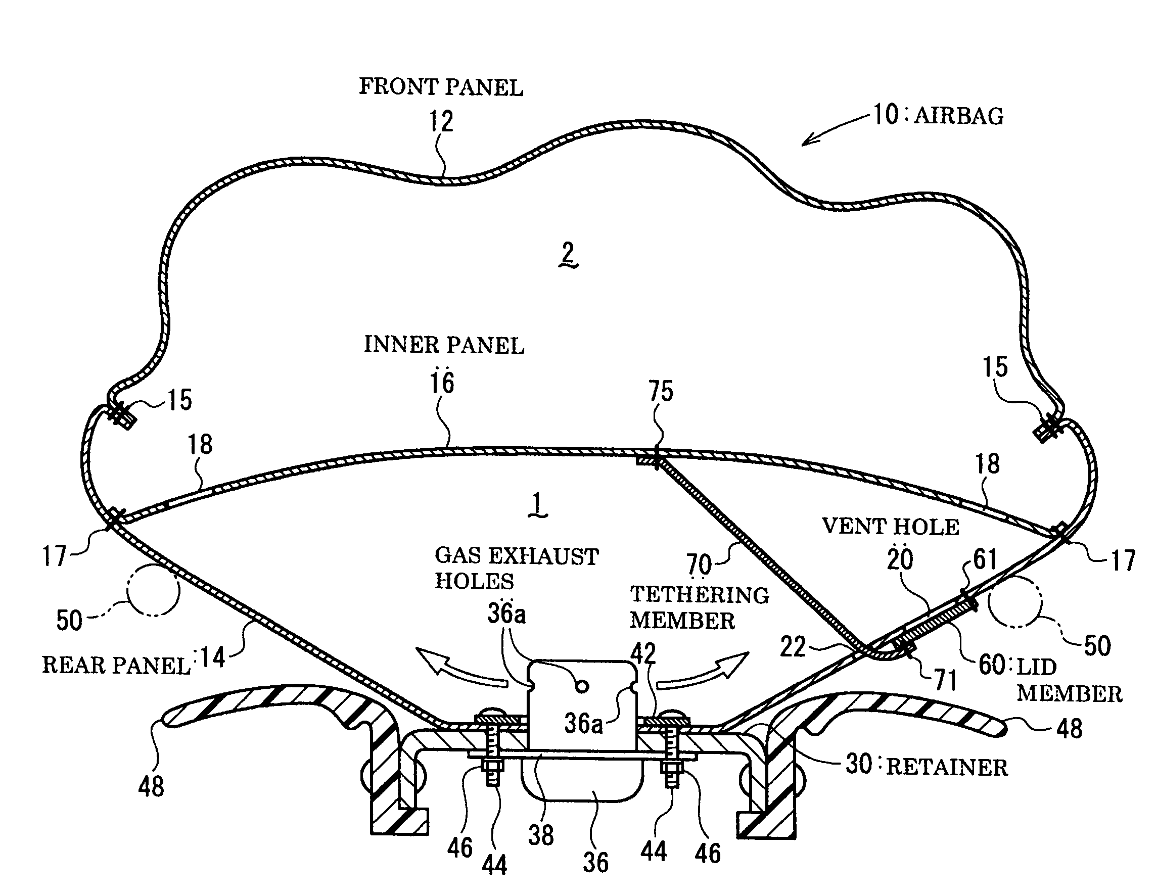
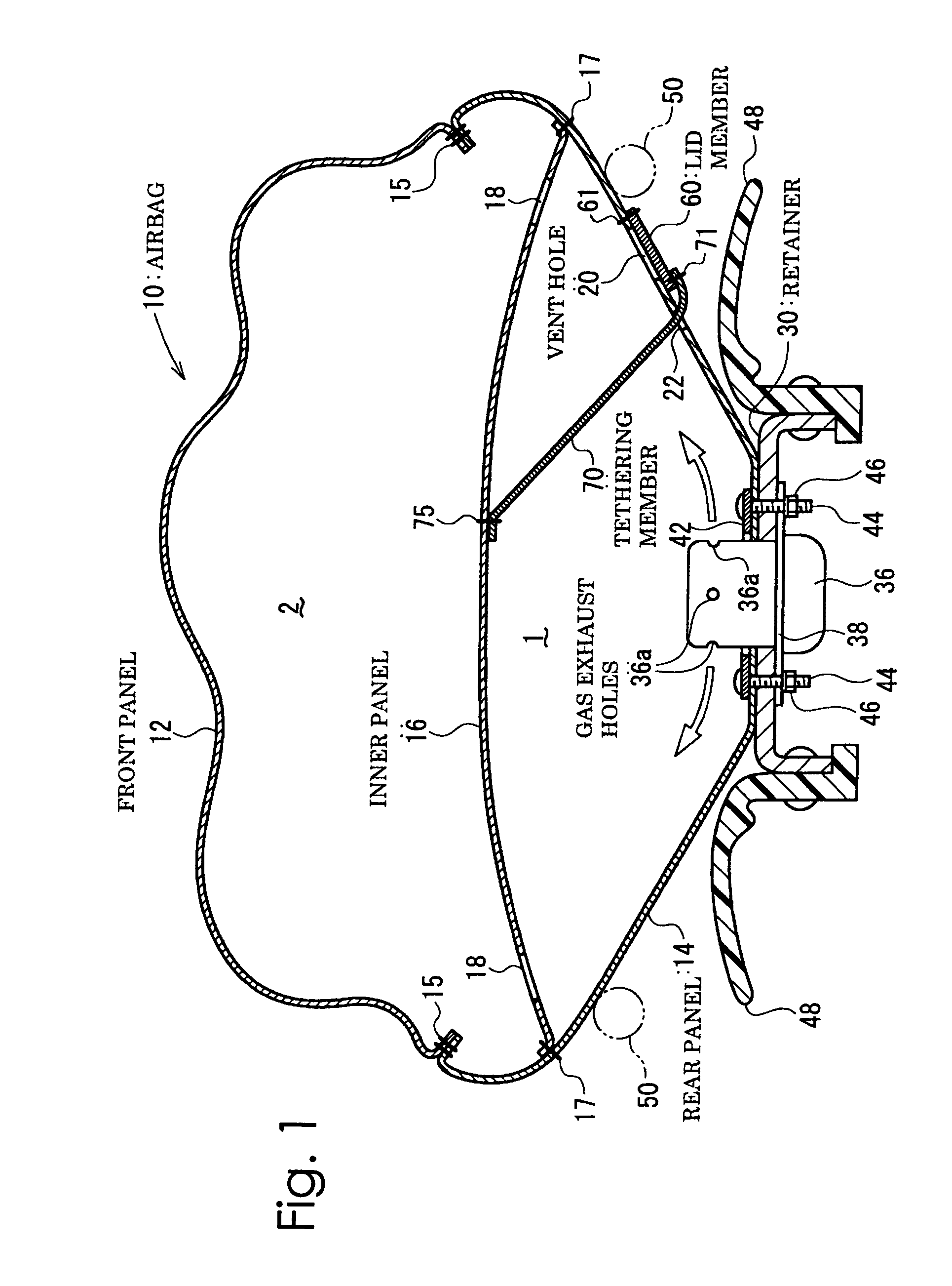
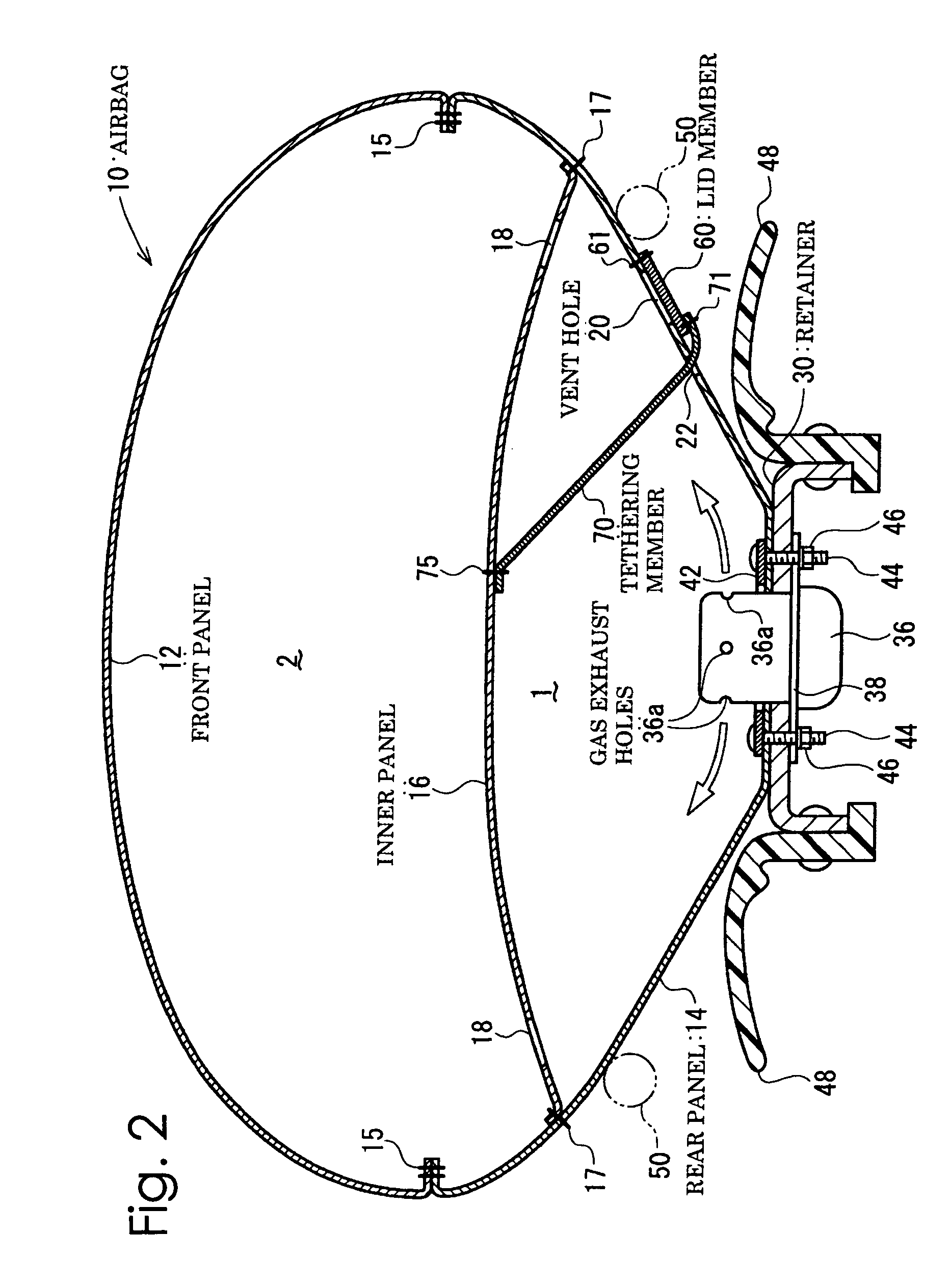
[0049]FIGS. 1 through 4 are sectional views of an airbag and an airbag apparatus comprising the same according to an embodiment corresponding to the first aspect through sixth aspect and the eighth aspect of the invention, showing respective states during the inflation. FIG. 1 shows an early stage of the inflation in which the inner pressure of a first chamber is higher than the inner pressure of a second chamber. FIG. 2 shows a stage just before gas generation of an inflator is ended, and FIG. 3 shows a stage when the vent hole is opened. In addition, FIG. 4 shows a state when an out-of-position occupant collides with the airbag during inflation.

[0050]In this embodiment, the airbag 10 is a driver-side airbag which is inflated and deployed from a steering wheel 50 toward an occupant.

[0051]The airbag 10 comprises a front panel 12 composing an occupant-side surface, a rear...


PUM


Abstract

An airbag device includes an outer shell forming an airbag and having a vent hole, a restriction member for restricting gas flow through the vent hole, a first chamber having the vent hole, a second chamber, the inner panel partitioning the airbag into the first and second chambers and having a communication portion, and a tether member for connecting the restriction member and the inner panel. Gas is introduced into the first chamber and then into the second chamber. When the first chamber is filled with gas and the inner panel is tensioned, the tension exceeding a predetermined value is applied to the restriction member so that the vent hole is substantially closed. When the first chamber is not filled with gas and the inner panel loosens, the tension applied to the restriction member does not reach the predetermined value so that the vent hole is opened.

Description

BACKGROUND OF THE INVENTION AND RELATED ART STATEMENT[0001]The present invention relates to an airbag which is structured to restrict gas flow from the airbag through a vent hole. Further, the present invention relates to an airbag apparatus comprising the airbag.[0002]It is well known to form a vent hole in an airbag to release gas from the inside of an inflated airbag, whereby the vehicle occupant is softly received by the airbag.[0003]Japanese Unexamined Patent Application Publication No. 2005-199987 (Patent Document 1) discloses an airbag in which a vent hole is covered by a lid member. In this publication, a proximal end portion, near an inflator (the center of the airbag) in relation to the vent hole, of the lid member is unreleasably connected to the airbag. In addition, a distal end portion, on the other side of the vent hole from the inflator, of the lid member is caught at the periphery of the airbag between a front panel (occupant side surface) and a rear panel (non-occup...

Claims


Application Information

Patent Timeline
Patent Type & Authority Patents(United States)
IPC IPC(8): B60R21/276
CPCB60R21/2338B60R21/239B60R2021/23382
Inventor ABE, KAZUHIROKUMAGAI, MASAYOSHI
Owner TAKATA CORPORATION
Why Eureka
Try Eureka