Controllable bi-circulating hot-pipe system

A dual-circulation, heat pipe technology, applied in indirect heat exchangers, lighting and heating equipment, etc., can solve problems such as the use effect is not as good as the one-piece heat pipe, insufficient working fluid conveying force, uneven liquid separation, etc., to facilitate continuous adjustment. And control, simplify the internal structure, solve the effect of insufficient conveying force

Inactive Publication Date: 2007-01-17
QINGDAO UNIV
1 Cites 52 Cited by

AI-Extracted Technical Summary

Problems solved by technology

[0004] The purpose of the present invention is to overcome the problems of insufficient working fluid delivery force, uneven liquid separation, use effect far inferior to the one-piece heat pipe and no control function of the separate heat pipe, that is, to propose a new "heat pipe system". The evaporation section and condensation section of the original "heat pipe element" are organically connected with several other necessary components to form an independent system to overcome the sho...

Method used

Condensate liquid supply and distribution subsystem: solution circulating pump 18 extracts liquid working medium from liquid storage tank 11, is delivered in liquid separator 16 through liquid delivery pipe 15, through liquid separator 16 and isometric The distribution tube bundle 8 evenly distributes the liquid working medium to each evaporation pipeline in the evaporators 7 and 23; its function is to evenly send the liquid working medium separated by the gas-liquid separator 14 to the evaporators 7 and 23 again. Evaporation is carried out in 23 to form a small cycle to ensure the efficient operation of the evaporator; at the same time, the liquid working medium condensed by the condenser 2 is also sent to the evaporators 7 and 23 to form a large cycle to complete the liquid working medium necessary for the heat pipe Transfer work from condenser to evaporator.
Embodiment 3: be the 3rd kind of embodiment structure of the present invention and work flow, its evaporator 7 and condenser 2 and condensate liquid supply and distribution, gas-liquid two-phase flow and separation, gas phase transport and distribution and The four subsystems of heat exchange control are exactly the same as those in Example 1, but the liquid phase collection and storage are different. In Embodiment 1, the condensate of the condenser 2 flows directly into the liquid storage tank 11 by gravity, so the installation height of the liquid storage device must be lower than the lowest point of the condenser. Adding a solution pump 20 on top allows the installation height of the condenser 2 to be lower than that of the liquid receiver 11, making the installation and arrangement of the condenser more flexible.
Embodiment 4: be the 4th embodiment structure of the present invention and work flow, its evaporator 7 and condenser 2 and condensate liquid supply and distribution, gas-liquid two-phase flow and separation, gas phase transport and distribution and The four subsystems of heat exchange control are exactly the same as in Example 2, but the liquid phase collection and storage are different. In Embodiment 2, the condensate of the condenser 2 flows directly into the liquid storage tank 11 by gravity, so it is required that the installation height of the liquid storage device must be lower than the lowest point of the condenser. Adding a solution pump 20 on top allows the ins...

Abstract

This invention relates to a double- cycle high efficient heat pipe heat exchanging system that can control the heat exchanging quantity. There are evaporator and condenser two types of heat exchangers. The number of each type is one or several that formed by connected in parallel. This system includes: condensate supplying and distributing system; gas-liquid two phases flowing and separating system; gaseous phase transmitting and distributing system, liquid phase collecting and storing system; heat exchanging quantity controlling system. The evaporator of heat pipe, condenser, gas-liquid separator, liquid storage, solution circulating pump, liquid distributor, the connecting pipeline and related controlling parts are connected together to form the double cycles controllable heat pipe system. The solution pump, liquid distributor, evaporator and gas-liquid separator are connected together to form independent working fluid cycle, which settle the problems that working fluid carrying capacity is not enough and liquid distribution is uneven.

Application Domain

Technology Topic

Image

  • Controllable bi-circulating hot-pipe system
  • Controllable bi-circulating hot-pipe system
  • Controllable bi-circulating hot-pipe system

Examples

  • Experimental program(8)

Example Embodiment

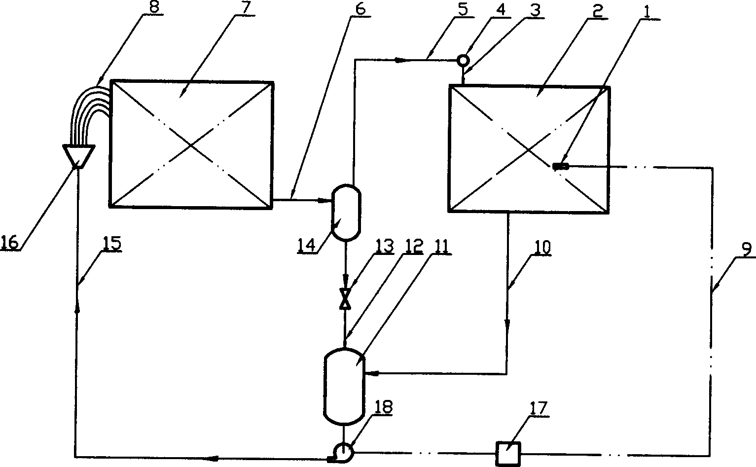
[0033] Embodiment 1: The structure and work flow of the first embodiment of the present invention. Its main components include an evaporator 7 and a condenser 2; it also includes a solution circulation pump 18, a liquid transport pipe 15, a liquid distributor 16, etc. Condensate liquid supply and distribution subsystem composed of a length of distribution tube bundle 8 and so on; gas-liquid two-phase flow and separation subsystem composed of two-phase flow conveying tube bundle 6 and gas-liquid separator 14; gas-phase working fluid passes through conveying pipe 5 , The gas phase conveying and distribution subsystem consisting of the gas phase working fluid main pipe 4 and the uniform gas distribution pipe 3; consisting of the pressure regulating valve 13, the gas-liquid separator liquid conveying pipe 12, the condenser condensate conveying pipe 10 and the liquid storage tank 11 Liquid phase collection and storage subsystem; a heat exchange control subsystem composed of a temperature sensor (or temperature sensing bag) 1, a temperature signal transmission line 9, and a temperature controller 17. The above-mentioned evaporator 7 and condenser 2 are organically connected with the five subsystems, and continuously transfer heat from the medium in contact with the evaporator to the medium in contact with the condenser, and the amount of heat exchange can be realized automatically. control.
[0034] The start-up and operation process of the system device is as follows: first install the dual-circulation controllable heat pipe system, evacuate and fill the heat pipe circulating working medium, start the liquid working medium circulating pump, and allow a certain amount of liquid working medium to circulate in the evaporator 7. Then turn on the heating source system of the evaporator and the cooling source system of the condenser, and the heat pipe will enter the normal working stage. In the normal working process, the solution circulating pump 18 extracts the liquid working fluid from the liquid storage tank 11, and transports it to the liquid distributor 16 through the liquid transport pipe 15. The liquid working fluid is uniformly transferred through the liquid distributor 16 and the equal-length distribution tube bundle 8. The working fluid is distributed to each evaporation pipeline in the evaporator 7. In the evaporation pipeline, the liquid working fluid absorbs the heat of the medium in contact with it, part of the liquid is vaporized, and enters the gas-liquid separator 14 through the two-phase flow pipe 6 After the gas-liquid separation, the liquid working medium flows through the regulating valve 13 and the gas-liquid separator liquid delivery pipe 12 back to the liquid storage tank 11, forming a small circulation of the liquid working medium; while the gas-phase working medium enters the gas distribution through the gas pipeline 5 The mother pipe 4 uniformly transports the gas to each pipe of the condenser 2 by the uniform distribution pipe 3. After complete condensation is achieved in the condensing pipe, the condensate is sent to the storage tank 11 by the condensate return pipe 10, A large cycle of heat pipe working fluid is formed; the two cycles are organically combined to form a double cycle heat pipe system. The function of the small cycle is to reasonably control or increase the circulating volume of the liquid working fluid in the evaporator 7, and solve the problems of insufficient conveying force of the original heat pipe working fluid, uneven liquid distribution, and low efficiency of the heat exchange surface of the evaporator; the large cycle is The heat is transferred from the medium in contact with the evaporator 7 to the medium in contact with the condenser 2 to complete the heat transfer process. The working fluid returned to the liquid storage tank 11 is sent to the evaporator again through the solution circulation pump 18, and the next heat exchange process starts again, and the cycle repeats in this way to continuously realize the heat transfer process. The technical solution for realizing heat transfer control of the heat pipe in this embodiment is: the temperature sensor 1 senses the temperature of the medium heated by the condenser 2, and the signal transmission line 9 transmits the signal to the temperature controller 17, which is in accordance with the regulations The control algorithm adjusts the solution circulation pump 18 to change the liquid circulation flow rate in the evaporator 7, thereby changing the amount of vapor generated in the evaporator 7, thus changing the condensation amount in the condenser 2 and realizing the heat transfer of the heat pipe的调。 The adjustment. When the solution pump stops running, the working fluid in the evaporator 7 is quickly evaporated, and then the heat exchange process is completely stopped, and the heat exchange amount is zero; as the flow rate of the solution pump gradually increases from zero, the output of the evaporator 7 The air volume gradually increases, and the heat exchange amount of the heat pipe heat exchange system gradually increases until it reaches a certain maximum value. The present invention uses this change process to realize the adjustment of the heat exchange amount of the heat pipe and forms a controllable heat pipe system.

Example Embodiment

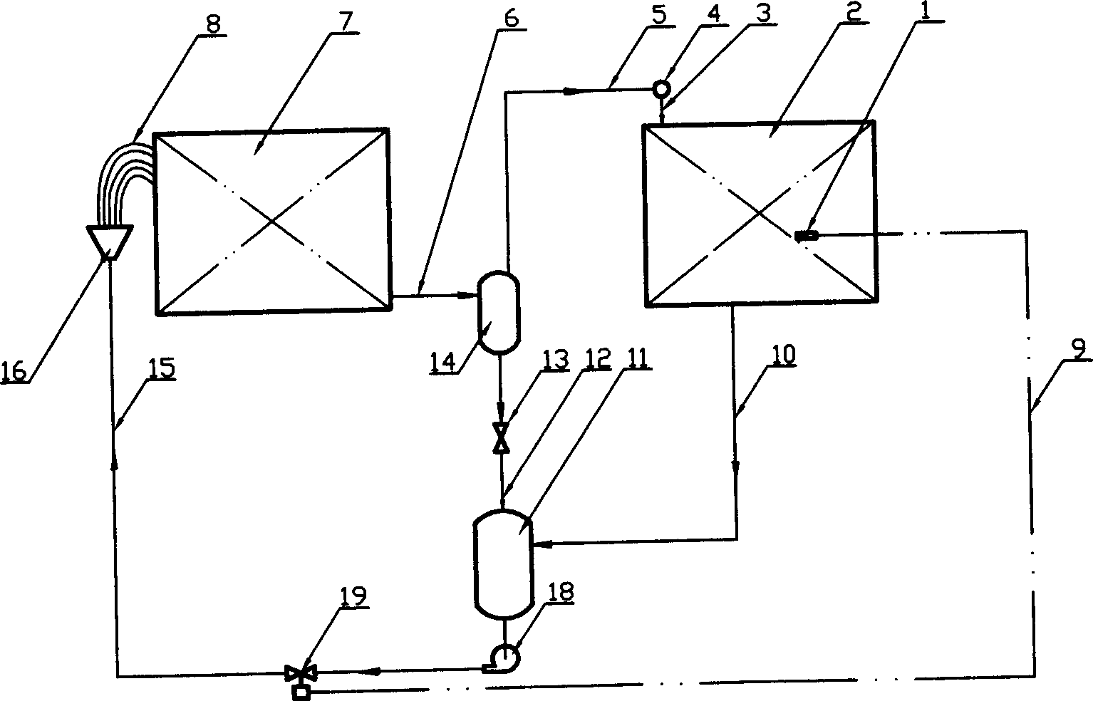
[0035] Embodiment 2: The structure and work flow of the second embodiment of the present invention. Its evaporator 7 and condenser 2 and condensate supply and distribution, gas-liquid two-phase flow and separation, gas-phase transportation and distribution, and liquid-phase collection The storage of the four sub-systems is exactly the same as in Embodiment 1, but the heat exchange control sub-system is different. Embodiment 1 uses a temperature controller 17 to control the rotation speed of the solution circulating pump to adjust the flow of the liquid working fluid. In this embodiment, a temperature regulating valve 19 is installed on the circulating solution delivery pipe 15. The temperature signal transmission tube 9 directly adjusts the flow rate.
[0036] The startup and operation process of this embodiment is the same as that of the first embodiment.

Example Embodiment

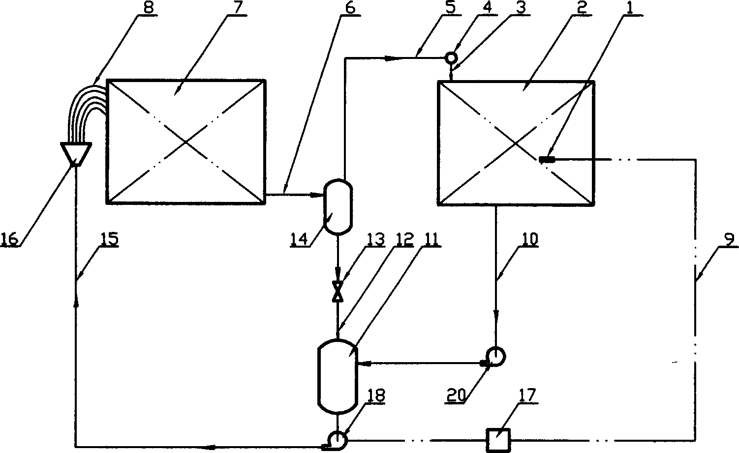
[0037] Embodiment 3: The structure and work flow of the third embodiment of the present invention. Its evaporator 7 and condenser 2 and condensate supply and distribution, gas-liquid two-phase flow and separation, gas-phase transportation and distribution, and heat exchange The control of the four subsystems is exactly the same as in Example 1, but the liquid phase collection and storage are different. In the embodiment 1, the condensate of the condenser 2 directly flows into the liquid storage tank 11 by gravity, so the installation height of the liquid storage must be lower than the lowest point of the condenser, and this embodiment uses the condensate return pipe 10 The installation of a solution pump 20 on the top allows the installation height of the condenser 2 to be lower than that of the accumulator 11, which makes the installation and arrangement of the condenser more flexible.
[0038] The start-up and operation process of this embodiment is the same as that of the first embodiment. After the condensate is formed in the condenser, the solution pump 20 should be started to keep the condenser 2 in a highly efficient working state.

PUM

no PUM

Description & Claims & Application Information

We can also present the details of the Description, Claims and Application information to help users get a comprehensive understanding of the technical details of the patent, such as background art, summary of invention, brief description of drawings, description of embodiments, and other original content. On the other hand, users can also determine the specific scope of protection of the technology through the list of claims; as well as understand the changes in the life cycle of the technology with the presentation of the patent timeline. Login to view more.

Similar technology patents

Classification and recommendation of technical efficacy words

  • Simple structure
  • Low cost

Microlithographic projection exposure apparatus

InactiveUS20050068499A1Simple structureReliable and low-maintenance operationProjectorsPhotomechanical exposure apparatusCamera lensPhysics
Owner:CARL ZEISS SMT GMBH

Semiconductor device

InactiveUS6975142B2Low costReduce manufacturing stepsTransistorSolid-state devicesVoltage amplitudeSemiconductor
Owner:SEMICON ENERGY LAB CO LTD
Why Eureka
Try Eureka