Cervical traction assembly with sensory feedback

a cervical traction and sensory feedback technology, applied in the field of cervical traction devices, can solve the problems of difficult for users to maintain an observable constant loading, complex and expensive devices available, and difficulty in maintaining observable constant loading

Inactive Publication Date: 2011-01-04
SKOWRON JOHN +2
View PDF4 Cites 13 Cited by
  • Summary
  • Abstract
  • Description
  • Claims
  • Application Information

AI Technical Summary

Benefits of technology

[0004]The present invention provides cervical traction assembly whereby the user can exert a variable load on the cervical spine and receive a sensory feedback when the traction is at or within range of a target load. The assembly includes a head harness wrapped around the forehead of the user that is attached to a traction bar connected to a load line assembly that passes through a direction reversal pulley and terminates with force straps actuated by the user's legs. The load line assembly includes a spring force scale that includes a control assembly that allows the user to set a target applied load and receive sensory feedback in the form of varying audible signals as the user applied load approaches, meets and exceeds a target load range.

Problems solved by technology

At a practitioner's office elaborate and expensive devices are available.
While beneficial under the operation of skilled personnel, these units are normally too complex and expensive for home use where it is recognized that therapeutic value is obtained through the regular use in accordance with prescribed protocols.
While providing versatility in loading, certain deficiencies are apparent.
Additionally, the scale load units are tightly spaced, making it is difficult for a user to maintain an observable constant loading.

Method used


Image

  • Cervical traction assembly with sensory feedback
  • Cervical traction assembly with sensory feedback
  • Cervical traction assembly with sensory feedback

Examples


Embodiment Construction

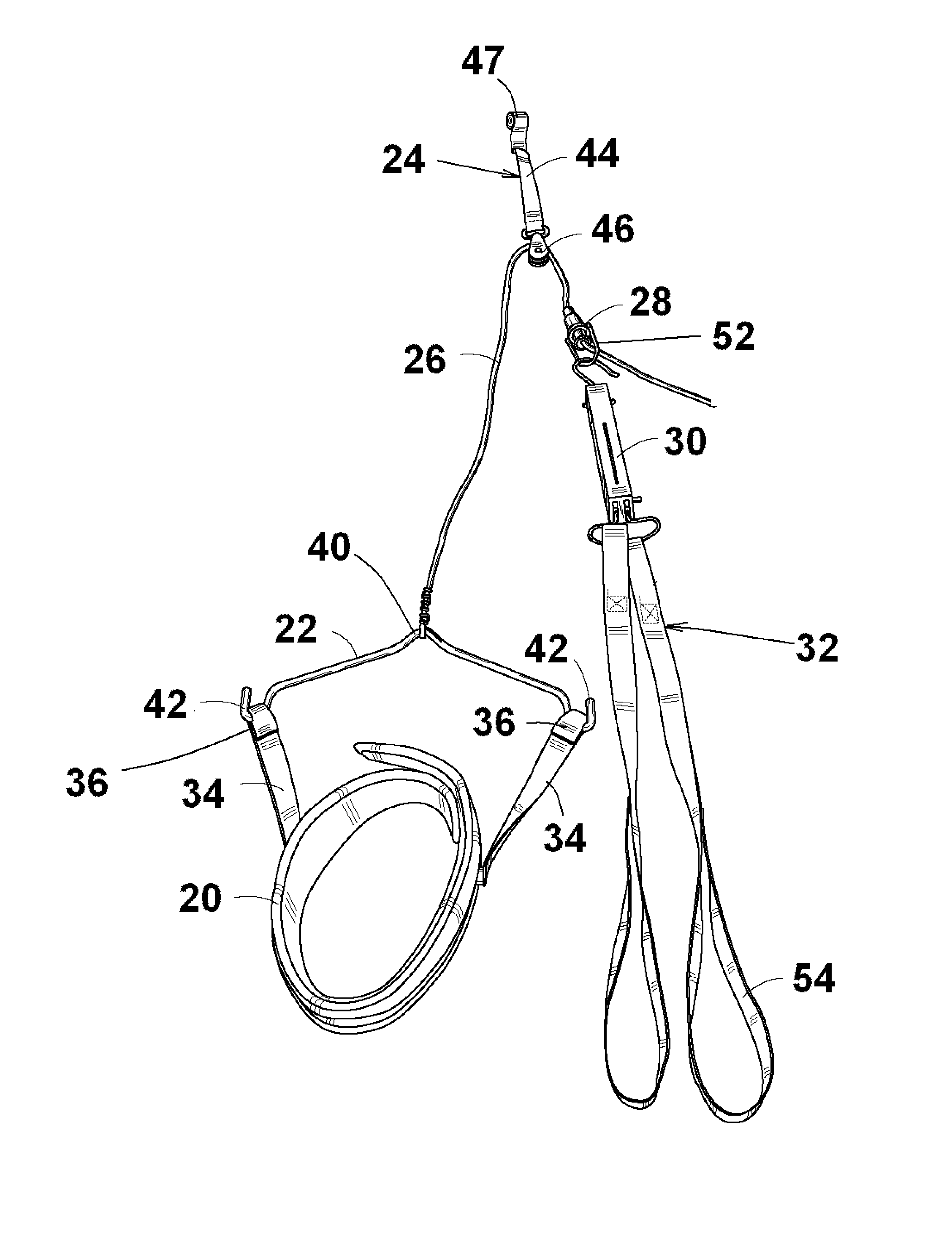
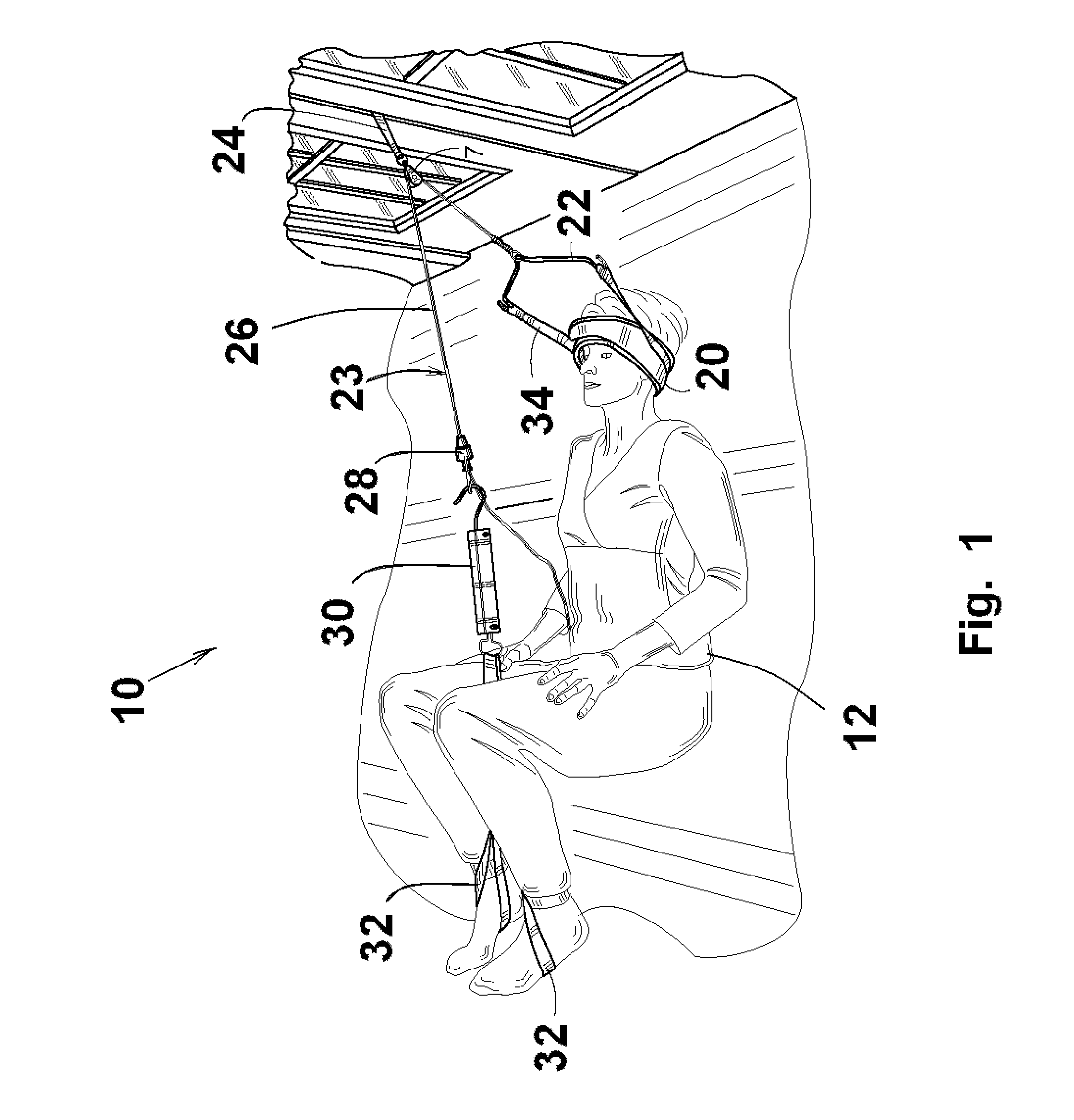
[0017]Referring to FIGS. 1 and 2, there is shown a cervical traction assembly 10 whereby a user 12 can self apply a variable and quantifiable traction loading to the cervical spine in accordance with a prescribed protocol and receive sensory feedback as the loading approaches, reaches and exceeds a predetermined applied load range.

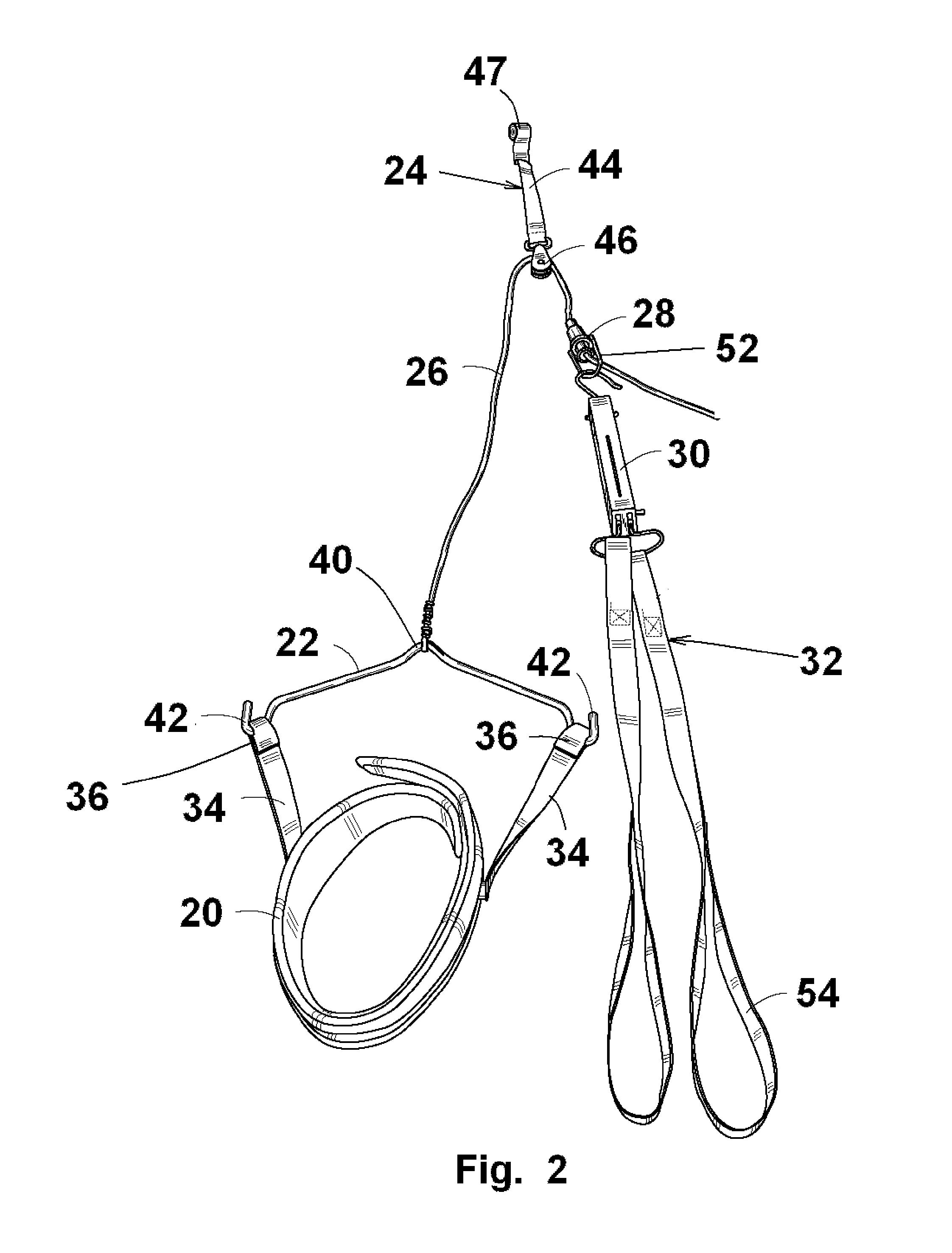
[0018]The cervical traction assembly 10 includes a harness 20 wrapped around the forehead of the user 12, a traction bar 22, and a load line assembly 23 including a mounting assembly 24, a load line 26, a line clamp 28, a force scale 30, and force straps 32.

[0019]The harness 20 is an elongated strap of a soft flexible material that is wrapped around the forehead of the user 12. The harness 20 has ends thereof attached by suitable fasteners such as hook and loop fastening systems. The harness 20 includes side straps 34 having distal end loops 36. The traction bar 22 is generally V-shaped having a pair of diverging side arms 38 integrally joined at an arcuat...


PUM


Abstract

A cervical traction assembly whereby the user can exert a variable load on the cervical spine and receive a sensory feedback when the traction is at or within range of a target load. The assembly includes a head harness wrapped around the forehead of the user that is attached to a traction bar connected to a load line assembly that passes through a direction reversal pulley and terminates with force straps actuated by the user's legs. The load line assembly includes a spring force scale that includes a control assembly that allows the user to set a target applied load and receive sensory feedback in the form of varying audible signals as the user applied load approaches, meets and exceeds a target load range.

Description

FIELD OF THE INVENTION[0001]The present invention relates to devices for applying cervical traction, and, in particular, to a cervical traction device wherein the user selects and applies a loading to the cervical area and receives audible feedback with respect thereto.BACKGROUND OF THE INVENTION[0002]Cervical traction devices are used for applying traction to the cervical spine. At a practitioner's office elaborate and expensive devices are available. While beneficial under the operation of skilled personnel, these units are normally too complex and expensive for home use where it is recognized that therapeutic value is obtained through the regular use in accordance with prescribed protocols.[0003]Many such devices have been available and generally rely on static weights applied at a harness wrapped around the user's head. It is also recognized that the use of intermittent and variable loadings provides additional advantages. One such traction device is disclosed in U.S. Pat. No. 4...

Claims


Application Information

Patent Timeline
Patent Type & Authority Patents(United States)
IPC IPC(8): A61F5/00
CPCA61H1/0218A61H2201/0173A61H2201/1607A61H2201/1642A61H2201/5007A61H2201/5061
Inventor SKOWRON, JOHNFEDORJAKA, JOHNSMITH, STEVE
Owner SKOWRON JOHN
Why Eureka
Try Eureka