

Pneumatic Augmented Reality Tactile Feedback Platform
a technology of augmented reality and tactile feedback, applied in the field of pneumatic augmented reality tactile feedback platform, can solve the problems of affecting the immersive experience of vr/ar, limiting the scope and functionality of current vr products, and significant delay
- Summary
- Abstract
- Description
- Claims
- Application Information
AI Technical Summary
Benefits of technology
Problems solved by technology
Method used
Image

Examples
example 1
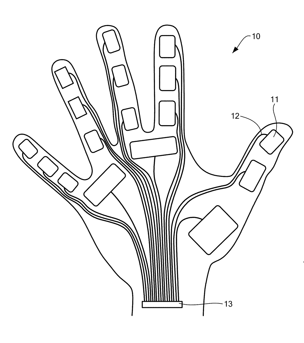
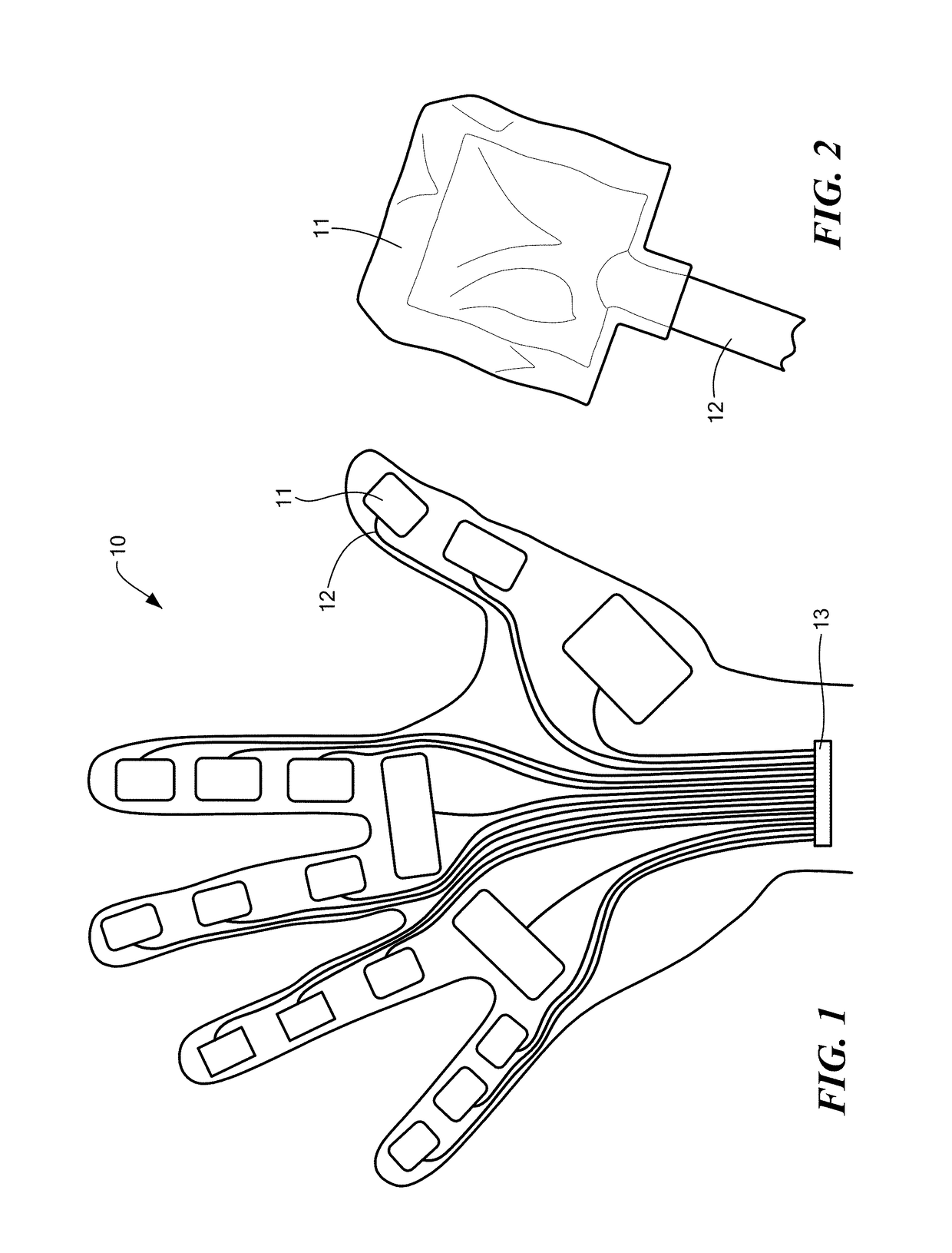
Glove Design
[0140]Heat sealed high impact polyethylene pouches sized to cover the surface area of each phalange of the hand were placed around the glove over the location of each corresponding phalange (12 in total). An additional two pouches were placed over the palm of the hand on the liner. A second nylon liner was placed over the pouches and sewn to the first liner to create a physical glove with inflatable pouches. Notches were cut in the second liner to allow for pneumatic cables to run between each pouch and the device. High impact polyethylene was chosen due to its tear resistance to allow the design to survive transport and careless use by a user as well as minimize the chances of rupture over frequent inflation / deflation cycles. The heat seal on the polyethylene as well as the plastic itself is rated to 30 psi which is far greater than the required 8 psi to feel that the pouch is fully inflated. 8 psi was experimentally determined to be the pressure where a user can't feel...
example 2
Pneumatic Hardware
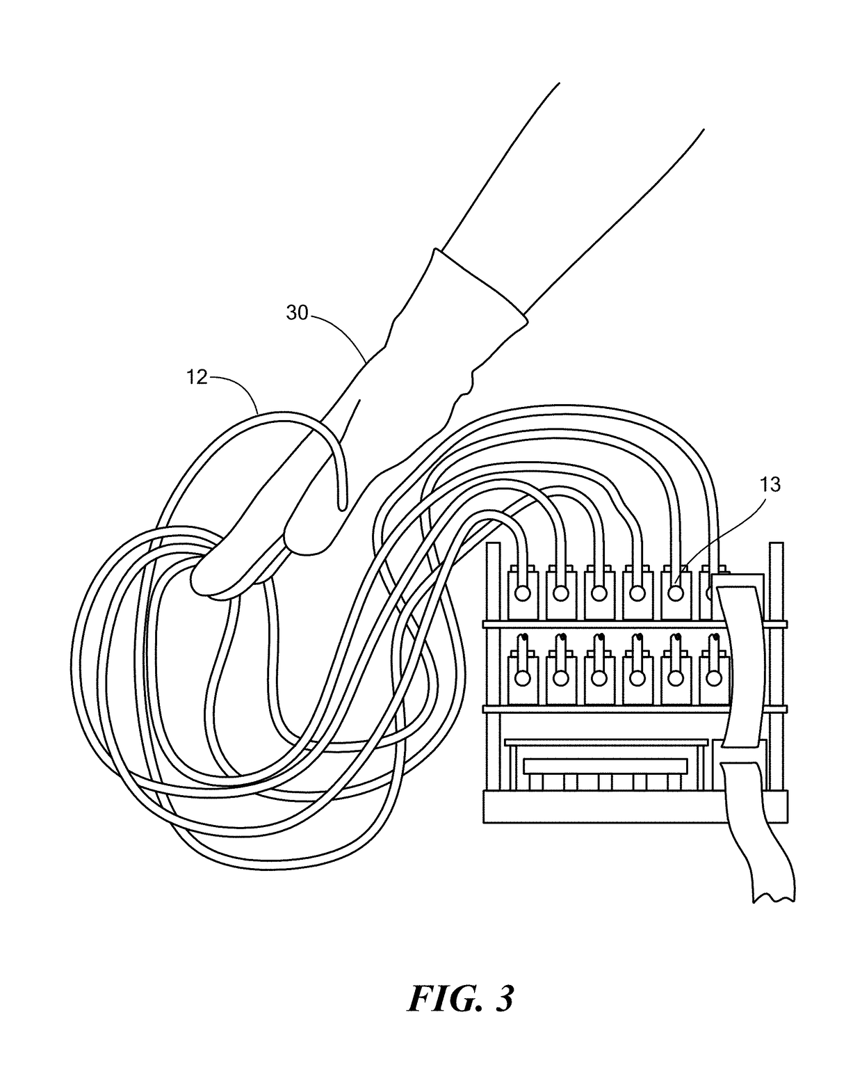
[0141]Pneumatic cables were connected to each pouch through a barbed fitting that protrudes through the pouch. Plastic epoxy was used to seal the air gaps between the fitting and the pouch. This fitting was designed to maintain a secure and airtight hold on pneumatic cabling. Barbed fittings were chosen since they come in smaller form factors than push to connect pneumatic fittings and tend to be less rigid, allowing for an overall smaller form factor to make the glove feel less clunky and more light. The cables were organized into bundles and routed over the back of the glove to the device since the application only tracked the front of the hand.
example 3
Pneumatic Pumps and Actuators
[0142]The structure of an open system is shown in FIG. 4. Air was compressed into a high pressure tank through a diaphragm pump, and an additional tank was connected to the vacuum end of the pump to create a negative pressure tank. A series of one way valves allowed air from the high pressure tank into each pouch for inflation during a virtual collision. An additional series of one way valves allowed for air to flow out of each pouch into the negative pressure tank when the user was no longer making contact with a virtual object. An additional valve released air drawn into the negative pressure tank to ambient, then the pump restored a vacuum in the negative pressure tank. Response times were between 25-30 ms.
[0143]A 12V Parker BTC high flow miniature diaphragm pump was chosen to pressurize the system. The pump can support up to 30 psi and has a high flow rate of up to 6 L per minute, thus ensuring a fast tank refill rate; however, a pump rated up to 10 ...
PUM
 Abstract
Description
Claims
Application Information