Customized in-ear interface for acoustic equipment and method

a technology of in-ear interfaces and acoustic equipment, applied in the field ofinear devices, can solve the problems of time and cost involved in producing customized in-ear interfaces, non-negligible amount of customized in-ear interfaces being rejected, and adding to the delay in receiving an end product by the consumer

Inactive Publication Date: 2011-01-04
SONOMAX HEARING HEALTHCARE
View PDF8 Cites 16 Cited by
  • Summary
  • Abstract
  • Description
  • Claims
  • Application Information

AI Technical Summary

Benefits of technology

[0012]Another object of the present invention is to provide a customized in-ear interface for a hearing aid and method of production that enables a customer to be fitted for the hearing aid in situ.
[0013]Therefore, in accordance with the present invention, there is provided an in-ear interface, comprising: an ear module shaped to be at least partially received in an ear canal, the ear module having a core defining a sound bore for enabling sound transmittance into the ear canal, a sheath covering a portion of an outer surface of the core so as to define an expandable space between the sheath and the core, and an opening defined in the core communicating with the expandable space whereby the expandable space is adapted to receive a settable compound to expand the ear module to the shape of the ear canal; and an insert secured to the ear module and having a slender portion received at least partially in the sound bore to generally maintain a shape of the sound bore during reception and curing of the settable compound in the expandable space.

Problems solved by technology

Also, the time and costs involved in producing customized in-ear interfaces is also an important design factor.
As a result, a non-negligible amount of customized in-ear interfaces are rejected by recipients claiming the product to be too uncomfortable to wear.
Accordingly, a delay results from these steps between the on-site model creation, and the reception and distribution of the end product to the consumer.
This also excludes the potential rejection by the consumer for lack of comfort of the in-ear interface or inefficient fit, which rejection adds to the delay in reception of an end product by the consumer.
Inefficient fitting of an in-ear interface results in the occurrence of feedback with present-day customized in-ear hearing aids.
These issues explain why present-day customized in-ear interfaces are costly.

Method used


Image

  • Customized in-ear interface for acoustic equipment and method
  • Customized in-ear interface for acoustic equipment and method
  • Customized in-ear interface for acoustic equipment and method

Examples


Embodiment Construction

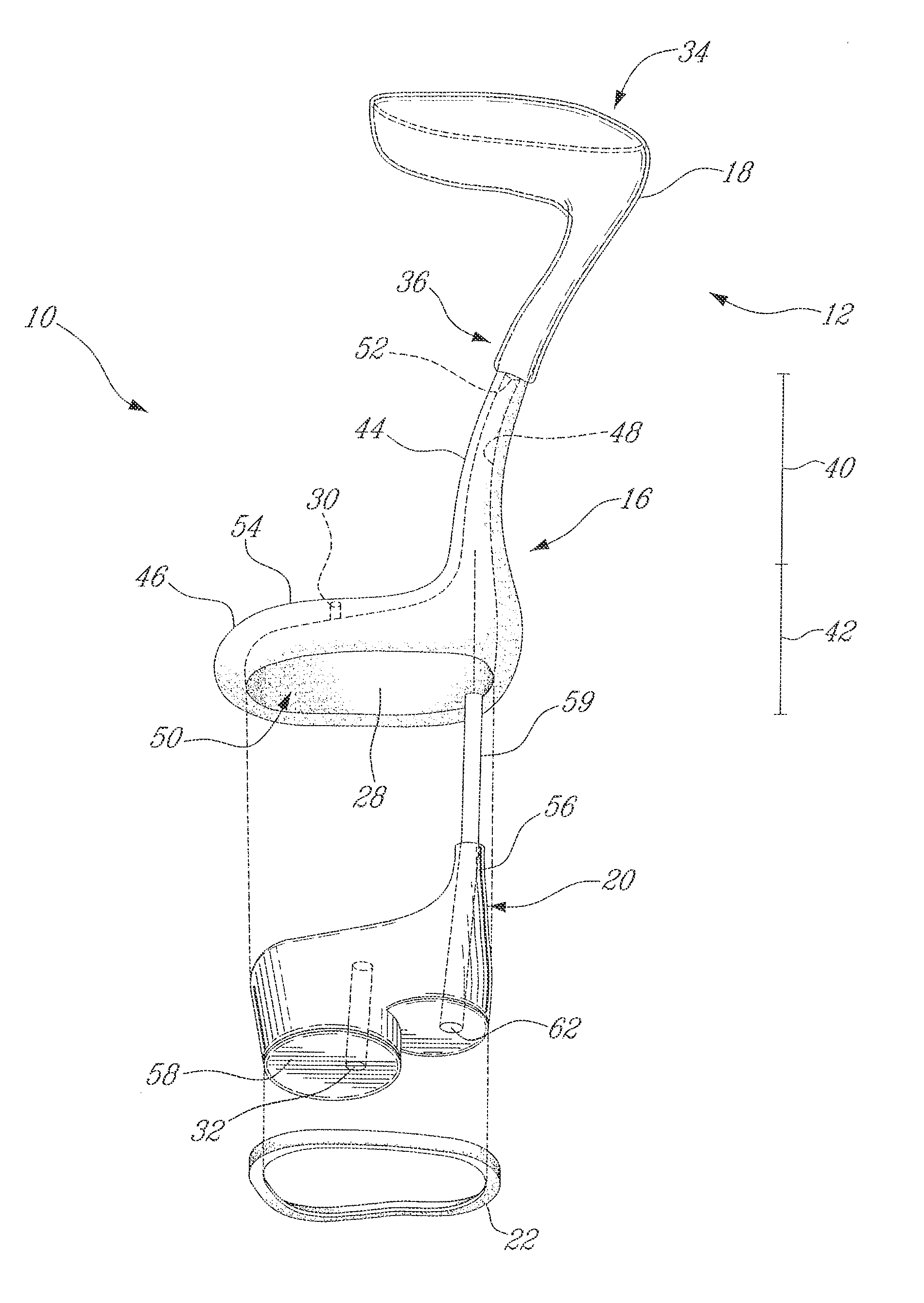
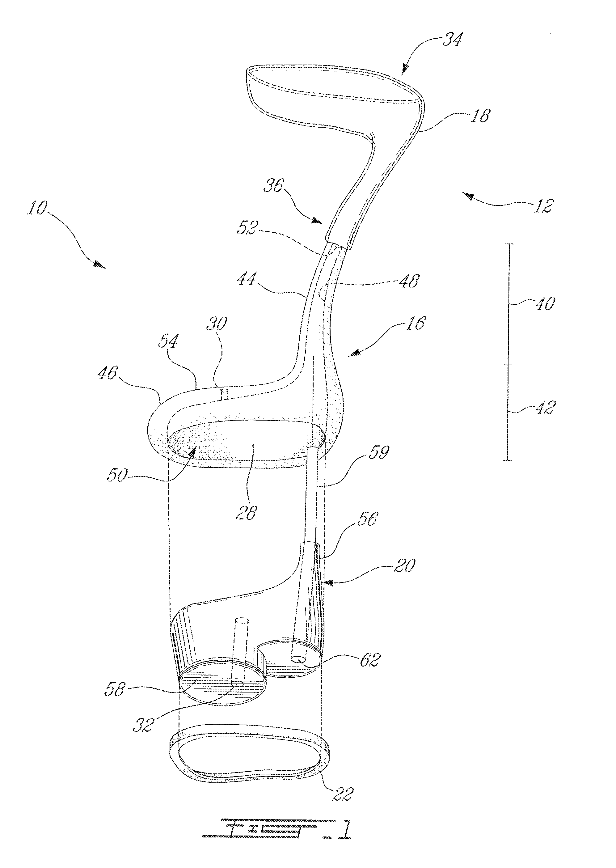
[0023]Referring to FIG. 1, there is shown an embodiment of an in-ear interface 10 for adapting acoustic equipment to an ear, for sound transmission or attenuation. According to a preferred embodiment, the in-ear interface 10 will be customized for customers following a sequence of steps described hereinafter, whereby it will be referred to hereinafter as “customized in-ear interface 10” notwithstanding the customizing phase at which the interface 10 is. The in-ear interface 10 consists of an expandable ear module 12 that is custom-fitted to an ear. The in-ear interface 10 also has various supporting components that are adapted for interaction with the ear module 12 and / or the acoustic equipment, to make the final product.

[0024]Referring to FIG. 1, the expandable ear module 12 is shown prior to being configured for customizing. The expandable ear module 12 is made up of a core 16 (e.g., a flexible core) with an integral stretchable sheath 18. According to one embodiment, the supporti...


PUM

PropertyMeasurementUnit
thicknessaaaaaaaaaa
sound transmittanceaaaaaaaaaa
shapeaaaaaaaaaa

Abstract

An in-ear interface comprises an ear module shaped to be received in an ear canal. The ear module has a core defining a sound bore for enabling sound transmittance into the ear canal. A sheath covers a portion of an outer surface of the core so as to define an expandable space between the sheath and the core. An opening is defined in the core communicating with the expandable space whereby the expandable space is adapted to receive a settable compound to expand the ear module to the shape of the ear canal. An insert is secured to the ear module and has a slender portion received at least partially in the sound bore to generally maintain a shape of the sound bore during reception and curing of the settable compound in the expandable space.

Description

CROSS-REFERENCE TO RELATED APPLICATION[0001]The present patent application claims priority on U.S. Provisional Patent Application No. 60 / 618,136, filed on Oct. 14, 2004, by the present applicants.BACKGROUND OF THE INVENTION[0002]1. Field of the Invention[0003]The present invention relates to in-ear devices such as hearing-aid devices, sound filter earplugs and the like, and more particularly to a customized in-ear interface for supporting acoustic equipment in an ear and a method for producing same.[0004]2. Background Art[0005]In-ear interfaces of many different types are found in various applications. Essentially, in-ear interfaces (also known as in-the-ear devices) are received in the ear canal so as to transmit or block selected sound / noise through selected acoustic equipment / electronics, such as microphones, receivers, speakers, micro-controllers and associated components. For instance, in-ear interfaces are part of hearing-aid devices, earplugs, headsets, audio transmitters, am...

Claims


Application Information

Patent Timeline
Patent Type & Authority Patents(United States)
IPC IPC(8): H04R25/00H04R31/00H04R25/02
CPCA61F11/08H04R25/652H04R25/658Y10T29/49572H04R2460/17H04R25/659
Inventor MCINTOSH, IANTURCOT, MICHAEL C.
Owner SONOMAX HEARING HEALTHCARE
Why Eureka
Try Eureka