
High-efficiency multiple probe imaging system

Inactive Publication Date: 2002-06-11
CAMBRIDGE RES & INSTR
View PDF33 Cites 208 Cited by
  • Summary
  • Abstract
  • Description
  • Claims
  • Application Information

AI Technical Summary

Benefits of technology

A third exposure may be taken in a third filter state, which has a wavelength response that is linearly independent of the first two states, such as a triangle wave, a non-linear ramp, or a high-order sinusoid. Mathematically, this state is linearly independent from the first two states. Adding this exposure allows resolution of very densely-spaced probes, or enables unambiguous determination of probe species and proportions when a given pixel contains a mixture of two probes.
A key benefit is that in many instances fewer than N exposures are required in order to resolve N species. A second benefit is the high efficiency of the system. One of the filter states can be essentially a clear state, with transmission in excess of 80% if desired. The other filter states can have equally high peak transmissions, with transmission at other wavelengths depending on the filter state (ramp, triangle shape, and so on).
Another benefit is that the cost and complexity of the system are greatly reduced relative to prior-art LCTFs, AOTFs, or interferometers. While it is possible to construct the present invention using an interferometer as the filter element, in preferred embodiments the filter may consist of one or two filter stages as described in U.S. Pat. No. 5,892,612, "Tunable Optical Filter with White State". Or, simple liquid crystal variable retarders between polarizers may employed instead. Generally, only one or two liquid crystal elements are required for the present invention, in contrast with prior-art LCTFs for multispectral imaging, which require from 5 to 12 elements. This reduces construction costs, and since the resulting assembly is typically only 3-6 mm thick, it is readily incorporated into microscopes, macroscopic imaging systems, and cameras without relay optics.
The use of liquid crystal elements as filters has several benefits. Unlike mechanically-scanned interferometric systems, there are no moving parts or precision optical surfaces, nor is the present invention sensitive to ordinary thermal drift. Unlike AOTF systems, no radio-frequency (RF) signals are required, and a large aperture is easily achieved. As with all LCTF imaging systems, diffraction-limited images may be readily obtained. This is a benefit in applications such as FISH, genetic therapy, functional imaging, chromosomal imaging, histological imaging, and the like.
Alternatively, one may use a filter wheel which is populated with filters made using colored glass, colored plastic, dielectric type filters, gels, and combinations of these. In a preferred embodiment of this type, one filter position is empty to provide a substantially clear state. Another filter provides a non-bandpass filter response such as a ramp or a periodic function of wavelength. It is easy to use software post-processing to spatially register images taken through each of the other filters relative to the clear state, as whatever features are present in a given filtered image must also be present in the unfiltered image, which transmits light from all probes. This eliminates the need for multiply-labeling certain species to produce a fiducial signal for registration purposes, as is required in the prior art. Even if no clear state is used, the fact that the filters have slope-type response functions, rather than bandpass-type functions, insures that several probes will be visible through any given filter, and vice versa. So again spatial registration is not a problem, and the prior-art limitation of needing a multiply-labeled fiducial is overcome.
Independent of the type of filter used, a further benefit is that the system obtains highly accurate data without requiring a high degree of uniformity in the imaging sensor employed. Also, the system can normally be used in a self-calibrating fashion, where the properties of the probes and filters are characterized in-situ and variations in chemistry are readily accommodated. Yet another benefit is that the system does not have burdensome computation requirements.

Problems solved by technology

Yet this is hardly an integrated, efficient solution to the problem.
However, all the foregoing imaging suffer from significant limitations.
Imaging spectroscopic methods require complex and rather expensive hardware, and involve taking at least N exposures, using optical elements of relatively low efficiency.
Multiple, long exposures are required, which limits throughput and is impractical with probes that photobleach rapidly.
However, this system has several weaknesses.
First, since the photometer bands are inherently much narrower than the emission spectrum of any given probe, only a small portion of the radiant energy from the sample is actually sensed.
This leads to reduced optical sensitivity.
Second, it is exquisitely sensitive to shifts in the wavelength of emission by the probes, as a shift of one-eighth of the emission width could lead to misidentification of which species was involved.
Yet there is no way to use this photometer with more widely-spaced probes, as it relies on the overlap of at least N-1 of the N species within each of the two photometer bands.
These photometric wavelength-detection systems are inherently non-imaging, in that they provide a wavelength indication for the whole beam of light, and cannot determine the wavelength at a plurality of separate points within an image.
However, in the vast majority of bio-medical applications, this is a severe limitation.
Even in gel chromatography, this results in poor utilization of equipment.
The plate reader is occupied for the entire duration of the gel separation, which can take hours; the alternative of a lengthy separation using an inexpensive instrument, followed by a rapid readout cycle in the more costly reader, is impossible.
However, for this purpose there is little reason to choose these systems over alternatives such as e.g. a fiber-coupled diode-array spectrometer, which would provide more reliable spectral information with better utilization of the scarce emitted photons.
The additional complexity of the scanner typically cancels out any innate simplification in the photometric wavemeter component.
In short, when coupled to a scanner, the result is a low-performance hyperspectral imaging system, with no clear benefits over the prior art in that realm.
Nor do any prior-art wavelength-measuring systems provide means for directly producing a two-dimensional image with a two-dimensional sensor.
Those which involve Fourier methods to determine wavelength are probably ill-suited to a taking a high-definition image, due to the computation requirements when the number of pixels is large.
Systems using two detectors face a significant cost burden over one-detector systems, as the cost of a two-dimensional imaging sensor such as a CCD is high.
Any error in the spatial registration of the multiple exposures degrades the numerical accuracy of the ratio scheme involved, since if readings from the two detectors come from different spatial regions in the sample, there is no way to take their ratio and determine a wavelength.
Spatial registration of two detectors to a fraction of one pixel is a challenging and expensive proposition.
This mechanical switching leads to image shift from the unavoidable wedge in the filter elements, which corrupts the ratio used to derive a wavelength measurement.
Other practical considerations confound the extension of existing point-measuring photometric systems into imaging systems.
The Prober photometer exhibits poor optical efficiency, since only a small portion of the sample emission is utilized by any given photometer band, even the most responsive band.
This deficiency is even more problematic in an imaging system, where the desire for high spatial resolution favors the use of imaging detectors with many pixels; this in turn means that the radiant energy is partitioned between a great number of pixels, which exacerbates the signal-to-noise requirements.
This arrangement is not capable of imaging a two-dimensional scene.
Simply replacing the photodiode or photomultiplier tube (PMT) of Buican with a two-dimensional imaging detector such as a CCD, is impractical if not absolutely impossible.
In summary, the aforementioned art provides equipment and methods for hyperspectral imaging to produce high-definition images of multiple probes in a sample, but these require at least N observations to resolve N probes and use relatively expensive, optically inefficient hardware.
However, these are point-measuring systems that cannot provide an image of the sample unless one adds mechanical or optical scanning means, which undermines the cost and performance benefits of this approach.
And, attempts to extend this art to construct systems with two-dimensional imaging sensors are impractical for at least one of the following reasons in every case: the need for multiple imaging detectors; the need to register multiple images obtained from different detectors, or from a single detector with multiple filters, to much better than a single pixel; poor optical efficiency; the need for mechanical moving parts; intensive computing requirements; or, the need to operate at sample rates far above the capability of imaging detectors.

Method used


Image

  • High-efficiency multiple probe imaging system
  • High-efficiency multiple probe imaging system
  • High-efficiency multiple probe imaging system

Examples


fourth embodiment

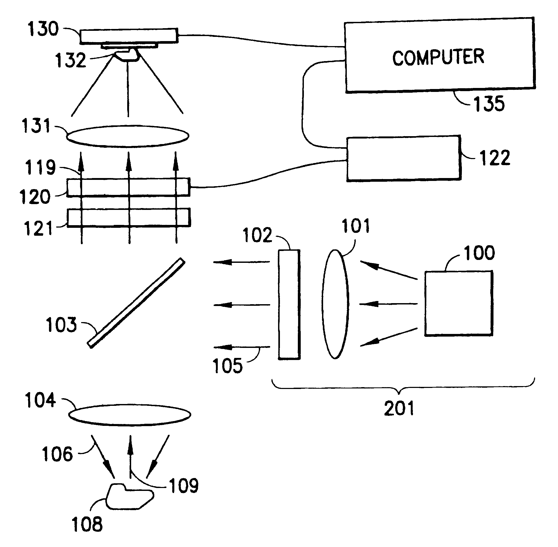
A fourth embodiment uses an infrared diode laser emitting at 940 nm as the excitation source; the epi-element and blocking filter reflect that wavelength while transmitting light with wavelengths .lambda.<630 nm. The sample is tagged with various probe species of up-converting reporter.

fifth embodiment

A fifth embodiment uses no illumination system 201 nor epi-illumination element 103 because the sample is bioluminescent, chemiluminescent, or otherwise luminous without need for an excitation light source.

sixth embodiment

A sixth embodiment uses a camera which contains three separate CCD detectors mounted with a trichroic prism. Means for assembling multiple CCD detectors with a common boresight are well-known in the art, and are used in high-end RGB cameras for video and scientific imaging. Or, firms such as Richter Enterprises (Wayland, Mass.) will design custom cameras of this type upon request. In this embodiment, the camera is a standard commercial RGB camera of this type, the Model DXC950 from Sony Corporation of America (Park Ridge, N.J.). Its trichroic prism directs red light to a first CCD detector, green light to a second CCD detector, and blue light to a third CCD detector. The images acquired by the three color planes are read out simultaneously with three sets of electronics within the camera fed to a three-channel RGB frame grabber. The detectors and prism optics are spatially registered at the time of manufacture so the same point in space is imaged to the same location on each of the ...


PUM


Abstract

An imaging system is disclosed which provides means for obtaining images with essentially diffraction-limited spatial resolution, and can distinguish between several species of probes within a sample. It may be used with fluorescent, luminescent, up-converting reporter, quantum dot, and other types of probes. Two or more exposures are taken through a filter which expresses different filter states, one of which is preferably a relatively neutral state with high transmission for all wavelengths of interest, and the others of which provide predetermined variation in transmission that are preferably sloping or periodic in wavelength. The probe species is identified by the ratio of response at the various filter settings.

Description

1. Field of the InventionThe present invention relates to equipment and methods for imaging a sample which may contain one or more species of luminous probes such as fluorescent probes, luminescent probes, quantum dot probes, up-converting probes, or other emissive probes; and more specifically, to equipment and methods which can image N species of probes with high optical efficiency, often requiring fewer than N observations of the sample.2. Description of the Related ArtIt is often of practical importance to image multiple luminous probes in a single sample, as in fluorescence in-situ hybridization (FISH), in chromatography plate readers, DNA sequencing, spectral karyotyping, general biological and neurobiological research, and the like.One approach to multiprobe imaging, taken by Glass et. al. in U.S. Pat. No. 5,723,294 is simply to image the sample, in this case a multiwell plate, in several plate readers one after another. By suitable choice of probes and reader settings, unamb...

Claims


Application Information

Patent Timeline
IPC IPC(8): G01N21/25G01N21/64
CPCB82Y10/00B82Y20/00G01N21/6456G01N21/6452G01N21/6428
Inventor HOYT, CLIFFORD C.LEVENSON, RICHARD M.MILLER, PETER J.
Owner CAMBRIDGE RES & INSTR
Learn More