Control device for slat blinds

a control device and blind technology, applied in the direction of door/window protective devices, shutters/movable grilles, gearing, etc., can solve the problem that the conventional lifting and tilting mechanism does not have such a function

Inactive Publication Date: 2011-01-11
CHING FENG BLINDS INC CO LTD
View PDF24 Cites 38 Cited by
  • Summary
  • Abstract
  • Description
  • Claims
  • Application Information

AI Technical Summary

Problems solved by technology

Unfortunately, the conventional lifting and tilting mechanisms do not have such function.

Method used


Image

  • Control device for slat blinds
  • Control device for slat blinds
  • Control device for slat blinds

Examples


Embodiment Construction

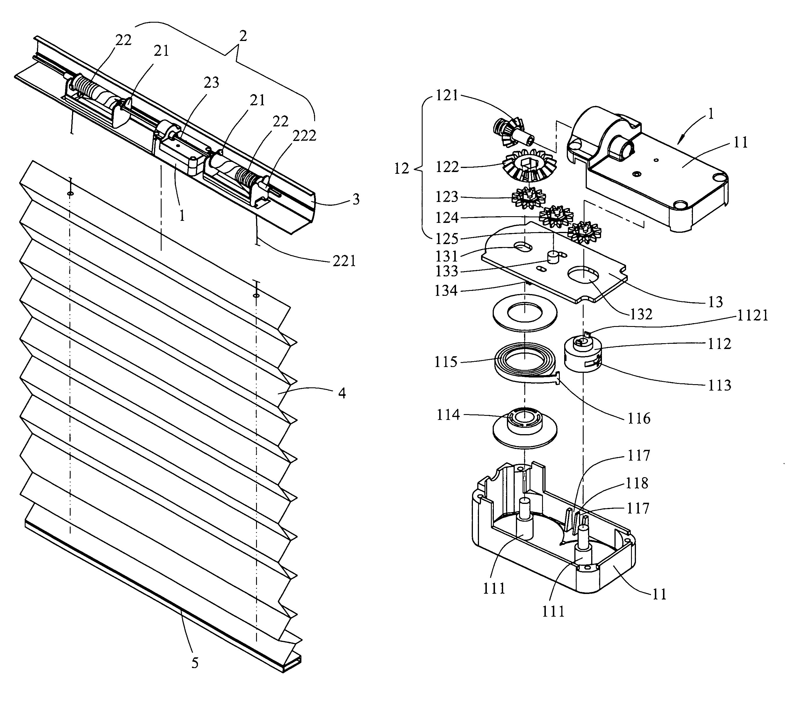
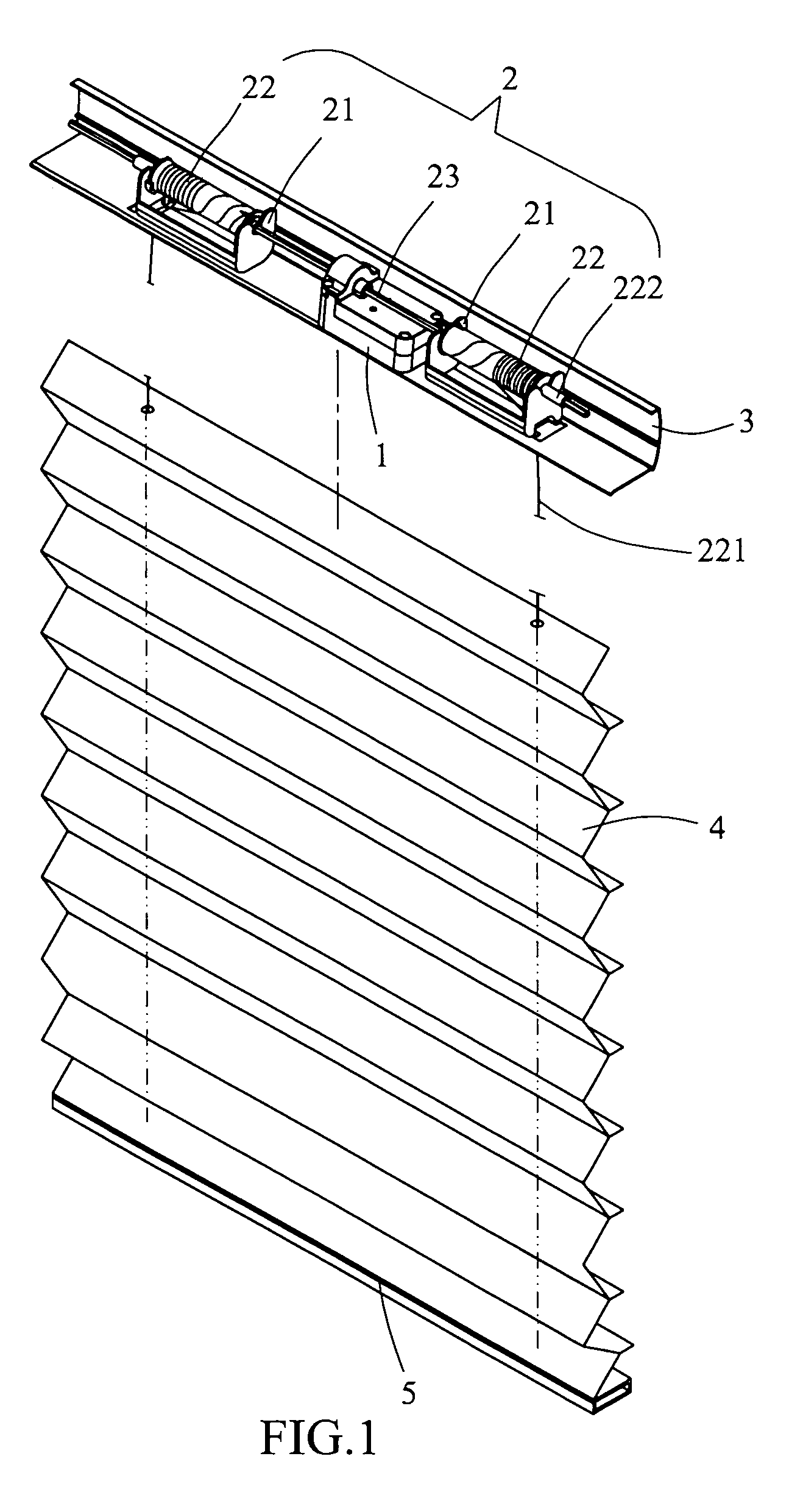
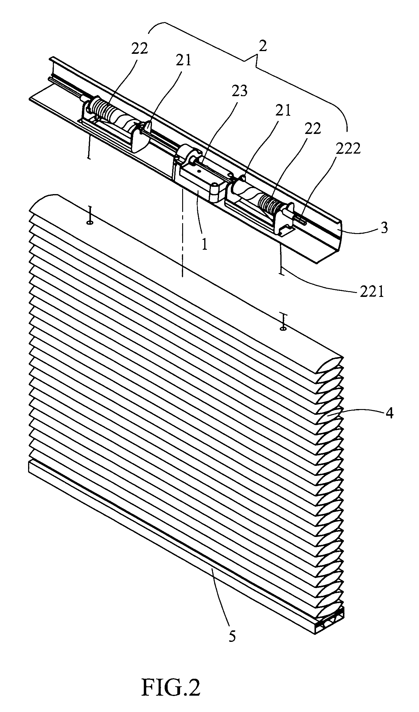
[0021]Referring to FIGS. 1 to 5, the control device for blinds of the present invention comprises a transmission unit 1, a scrolling unit 2 and a tilting unit, wherein the transmission unit 1, the scrolling unit 2 and the tilting unit are received in a box 3 located on a top of the blinds. The blinds include slats 4 connected by the lift cord 221 and the tilt cord 7, and a transverse bar 5 is connected to the lowest slat 4.

[0022]The transmission unit 1 includes a case 11, a coil spring 115 and a gear unit 12, wherein the coil spring 115 has a first end connected to the gear unit 12 and a second end of the coil spring 115 fixed within the case 11 so as to provide a force to keep the slats 4 at a desired height. The case 11 includes two posts 111 extending from an inner end thereof and two engaging recesses 117 are defined in an inside of each of two sidewalls thereof. A positioning plate 118 is located between the two engaging recess 117. A separation board 13 is located in the case ...


PUM


Abstract

A control device for blinds includes a transmission unit, a scrolling unit and a tilting unit, the transmission unit includes a case in which a coil spring and a gear unit are received. The coil spring is connected between the gear unit and the case. The scrolling unit includes two scrolling rods which are rotated with a transmission rod. Each scrolling rod has a lift cord wrapped thereon and extending through slats of the blinds. The tilting unit includes two tilt members connected to two respective end sections of the two scrolling rods. Two tilt cords have two respective positioning members which are clamped in two clamp grooves of the two tilt members and the tilt cords extend through the slats. The gears in the gear unit can be adjusted so as to cooperate with slats of different weights.

Description

FIELD OF THE INVENTION[0001]The present invention relates to a control device for slat blinds, and more particularly, to a lifting mechanism and a tilting mechanism for slat blinds.BACKGROUND OF THE INVENTION[0002]The slats of blinds can be adjusted by a conventional control device composed of a lifting mechanism and a tilting mechanism. The conventional lifting mechanism 8 of a slat blinds is shown in FIGS. 11 and 12, and generally includes an end cord 81 which has a curved end 811 and a cord wheel 82 on which a lift cord 83 is wrapped. The lift cord 83 includes a loop 831 formed on an end thereof so as to be tied with the curved end 811 of the end cord 81. A first wheel 84 is synchronically rotated with the cord wheel 82 and a coil spring 86 is connected between the first wheel 84 and a second wheel 85. The coil spring 86 is an S-shaped spring and one end of the coil spring 86 forms a coil 861 which provides a torque the same as the weight of the slats 9 so as to position the slat...

Claims


Application Information

Patent Timeline
Patent Type & Authority Patents(United States)
IPC IPC(8): E06B9/305E06B9/26E06B9/30F16H35/06F03G1/00
CPCE06B9/307E06B9/323Y10T74/1957
Inventor LIANG, WEN YINGHSU, SHENG YINGNIEN, WU CHUNGHUANG, CHIEN CHIH
Owner CHING FENG BLINDS INC CO LTD
Why Eureka
Try Eureka