Vehicle-mounted equipment carrier
a technology for equipment carriers and vehicles, applied in the field of equipment carriers, can solve the problems of not being able to solve the problem very satisfactorily, unable to arrange the straps in a very simple and time-consuming way, and the appearance of the carrier is not attractive, so as to achieve simple and quick operation
- Summary
- Abstract
- Description
- Claims
- Application Information
AI Technical Summary
Benefits of technology
Problems solved by technology
Method used
Image
Examples
first embodiment
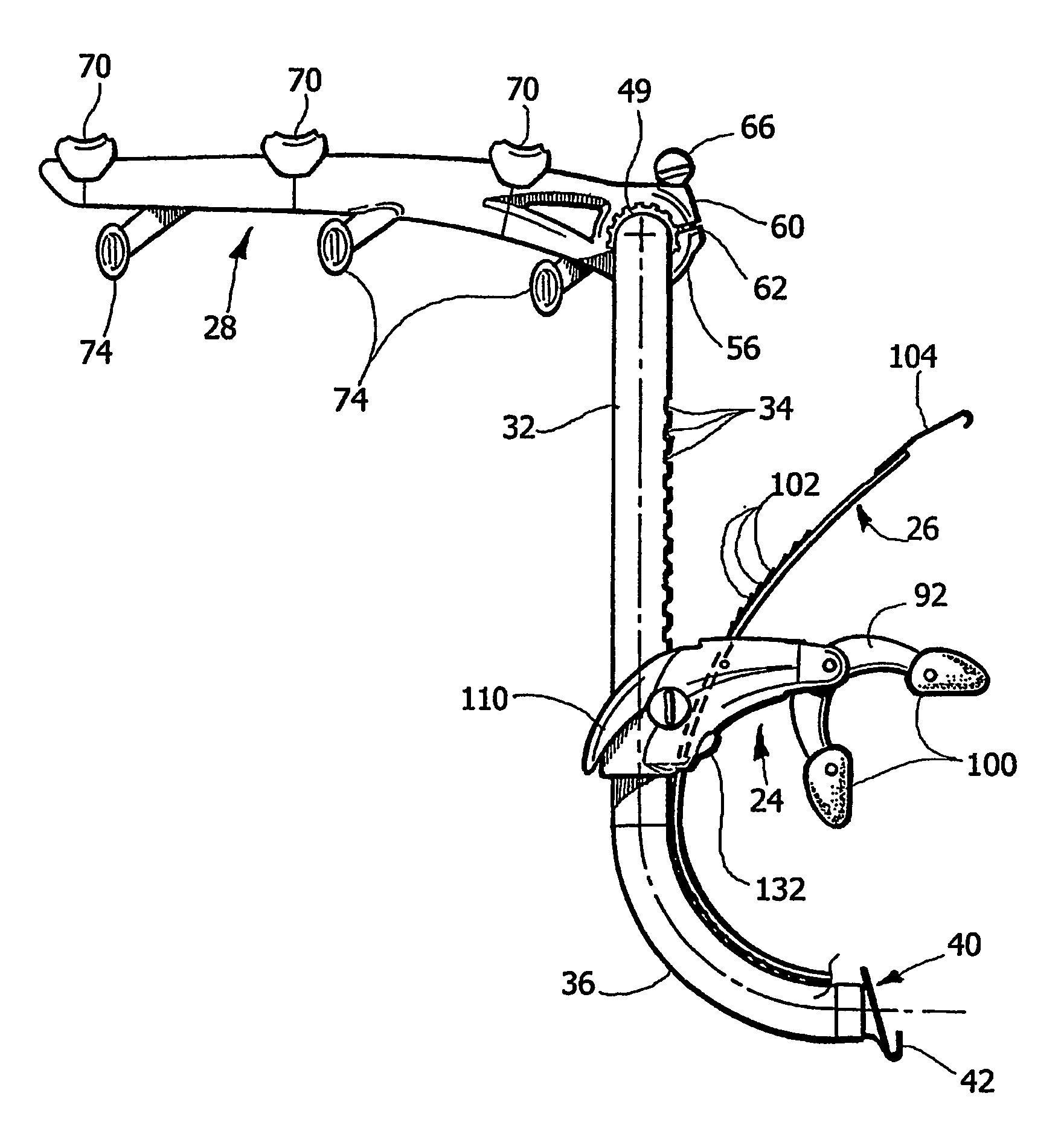
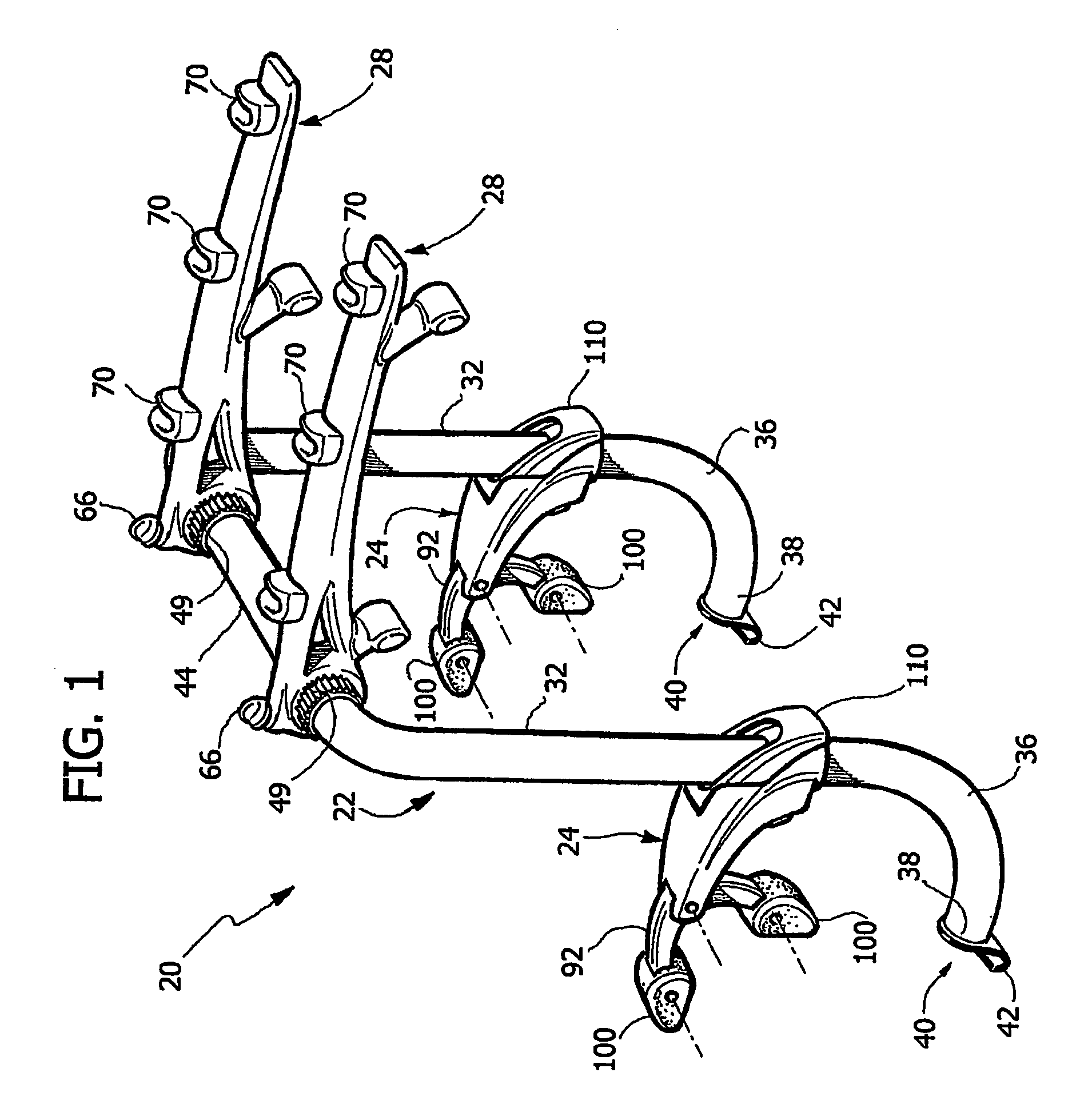
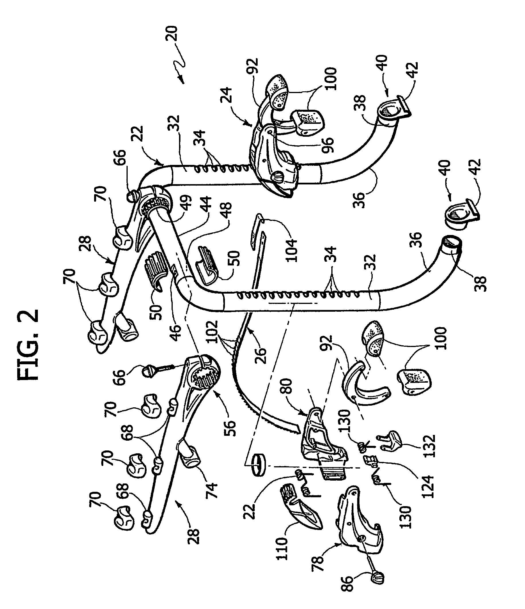
[0047]With reference to FIGS. 1-9, the invention is shown therein, in form of an equipment carrier 20 adapted for mounting to a vehicle for supporting various items on the exterior of the vehicle. Equipment carrier 20 generally includes a frame 22, a pair of supports 24 each of which includes a strap 26 (see in particular FIGS. 2,3,7), and a load-carrying arrangement engaged with frame 22, e.g. a pair of support arms 28.
[0048]In the illustrated embodiment, frame 22 includes a pair of upright sections 32 having forwardly facing spaced indentations 34. A curved lower section 36 extends from the lower end of each upright section 32, and terminates in a forwardly facing end 38. An engagement member 40, which includes a hook 42 at its lower end, is engaged with the forwardly facing end 38 of each lower section 36.
[0049]A cross-member 44 extends between and interconnects the upper ends of upright sections 32. Cross-member 44 includes provisions for mounting the equipment-carrying componen...
second embodiment
[0071]With reference to FIGS. 15-26 the invention is shown therein. In these figures, parts corresponding to those of FIGS. 1-14 are designated by the same reference numerals.
[0072]With reference in particular to FIGS. 17, 18, a main difference with respect to the carrier of the first embodiment lies in that each of the two straps 26 is stored in a wound configuration within the body of the respective support 24 when not in use.
[0073]With reference to FIG. 17, engagement member 40 includes a sleeve portion 41 which is freely rotatably mounted around the lower end 38 of the respective upright section 32. A rivet 420 (see FIG. 27) has its ends secured to two facing circular holes 422, one of which is formed at the top of sleeve portion 41, the other being formed in a tab 423 which is cut and bent away from the front wall of element 40 so as to engage the end portion 38 of the frame tube from below. The rivet is also engaged through two facing slots 421 formed on the upper and lower si...
PUM
 Abstract
Description
Claims
Application Information
 - R&D
- Intellectual Property
- Life Sciences
- Materials
- Tech Scout
- Unparalleled Data Quality
- Higher Quality Content
- 60% Fewer Hallucinations
Browse by: Latest US Patents, China's latest patents, Technical Efficacy Thesaurus, Application Domain, Technology Topic, Popular Technical Reports.
© 2025 PatSnap. All rights reserved.Legal|Privacy policy|Modern Slavery Act Transparency Statement|Sitemap|About US| Contact US: help@patsnap.com


