
Electrical locking hub nut

a technology of locking hub and hub nut, which is applied in the direction of cable junction, cable installation, cable fitting, etc., can solve the problems damage to wire insulation and/or removal from sections, and damage to wire insulation. , to achieve the effect of double labor cost, actual expense and efficiency

Active Publication Date: 2011-01-11
R&D HLDG
View PDF11 Cites 4 Cited by
  • Summary
  • Abstract
  • Description
  • Claims
  • Application Information

AI Technical Summary

Benefits of technology

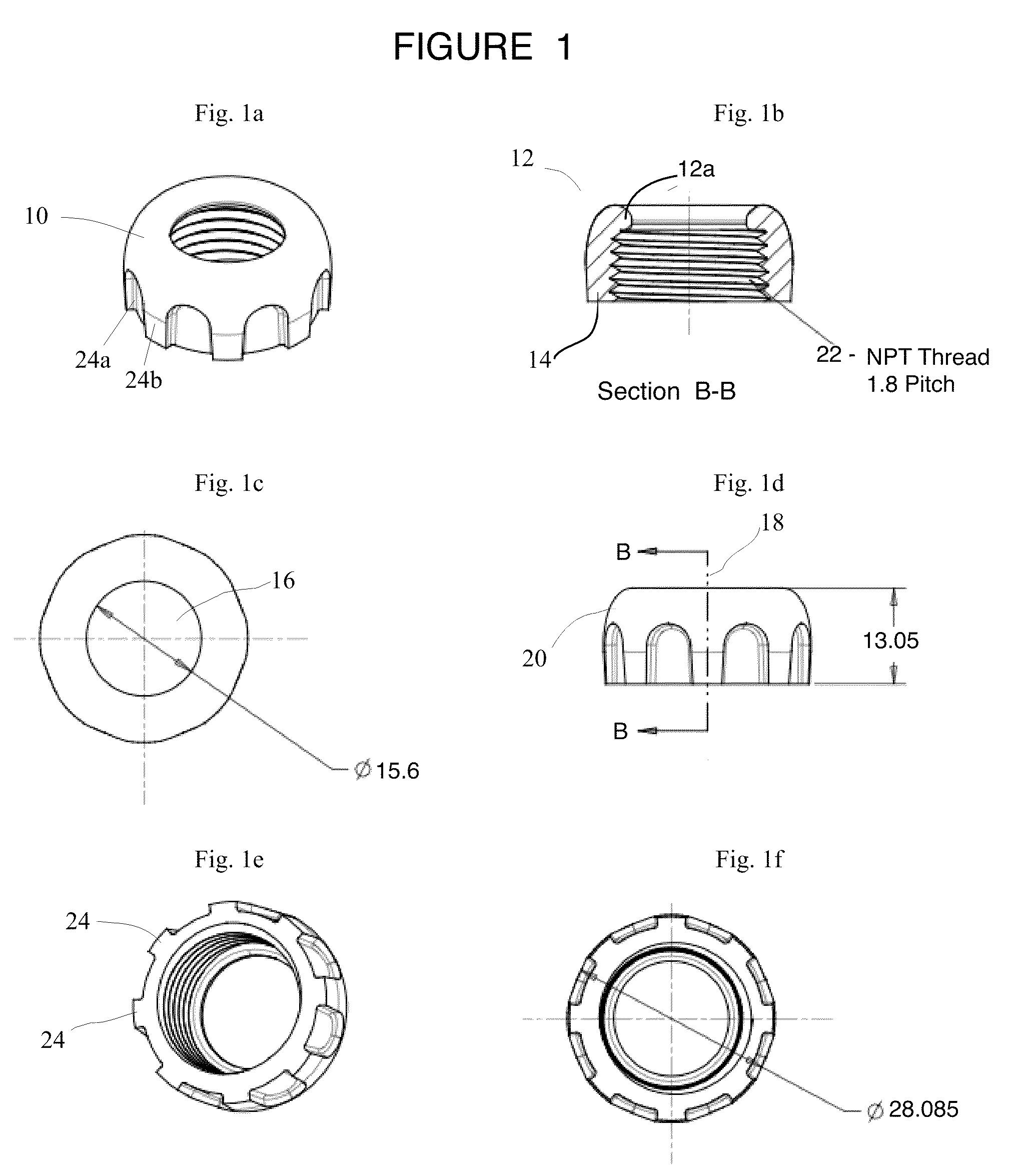
[0013]Accordingly, provided herein in order to address problems in the prior art is an electrical connector for terminating an electrical conduit having a protective rounded rim to avoid wire insulation damage, comprising: a locking hub nut, wherein said locking hub nut is toroid-shaped and has a rounded end and a flat end, said locking hub nut having a central axial bore extending therethrough, said locking hub nut having an external surface having a plurality of ribs for cooperative engagement during conduit installation, wherein central axial bore is screw-threaded along an inner surface, wherein the rounded end has a rounded rim, said rounded rim having a substantially smooth surface and extending inwardly into the central axial bore, wherein upon threading wiring through the central axial bore the rounded rim guides the wiring travelling therethrough in such a manner that there is minimal interaction with any sharp edges while being pulled through a length of conduit and interacting with the locking hub nut during such a pull operation, and wherein the locking hub nut has a height from flat end to rounded end of from about 11 mm to about 16 mm and provides for engagement with a junction box without using a lock nut.
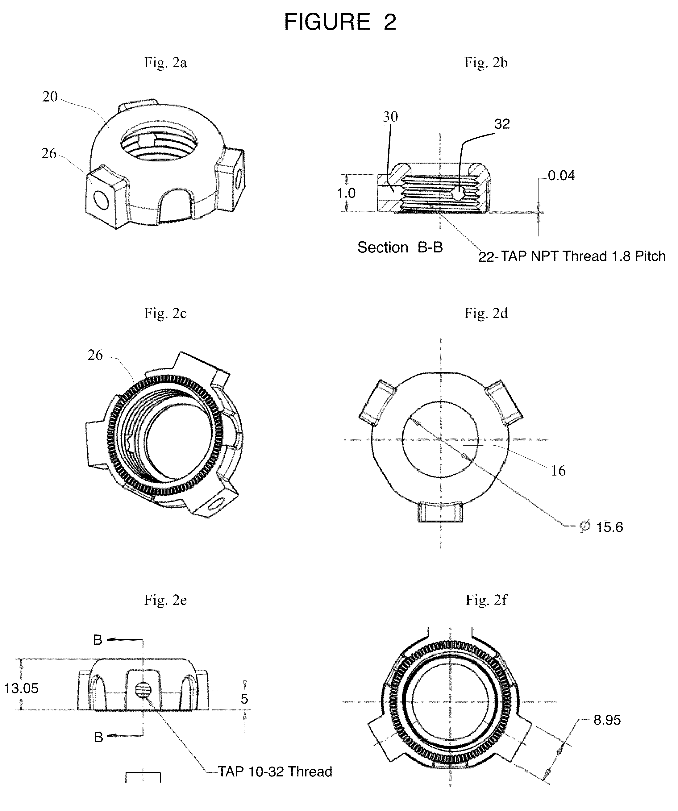
[0014]In a preferred embodiment, the electrical connector further comprises wherein flat end has gripping projections that allow the locking hub nut to engage with the junction box and increase the frictional interaction to substantially prevent unwanted rotation.
[0018]In a preferred embodiment, the electrical connector further comprises wherein the flat end has gripping projections that allow the locking hub nut to engage with the junction box and increase the frictional interaction to substantially prevent unwanted rotation.

Problems solved by technology

However, wiring is frequently damaged during such pulls due to the interaction of the wiring on the fittings that are used, often resulting in the wiring insulation being damaged and / or removed from sections.
Since the use and installation details for conduit are governed by various building codes, this kind of damage can make the difference between a successful inspection or an inspection that requires re-installation.
However, this doubles the labor cost both in terms of actual expenses as well as efficiency.
However, and although the plastic bushings are helpful for already installed wire, they are nonetheless sharp enough to damage wire during pulling and are not designed for this.
Significant problems also arise with the fittings.
For instance, snap-in electrical connectors are known to be problematic for having a loose electrical connection, which can be dangerous, and they allow contaminants to enter the connection.
Multipart connectors are known to be problematic for many reasons, including the inherent clumsiness of the required disassembly and reassembly, use for special tools for tightening, the potential of lost locknuts, cross-threading of the locknuts, the large amount of space used within the junction box, and the non-optional destruction of the connector that occurs during disassembly.

Method used


Image

  • Electrical locking hub nut
  • Electrical locking hub nut
  • Electrical locking hub nut

Examples


Embodiment Construction

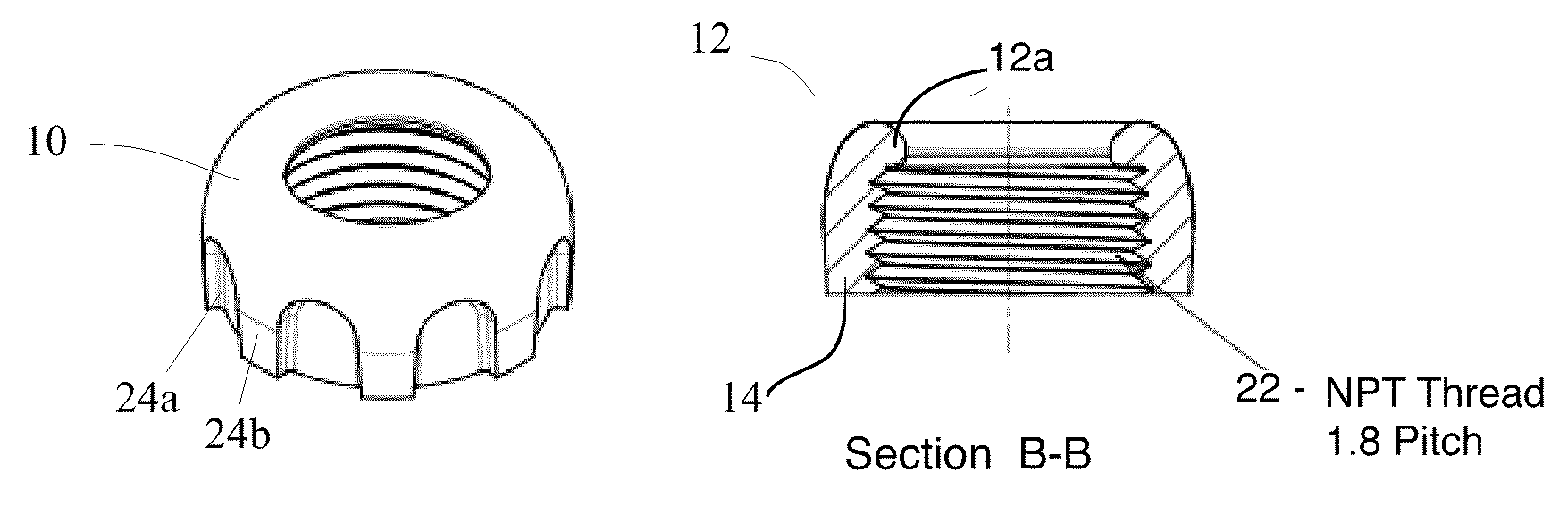
[0023]The locking hub nut 10 of the present invention is shown in FIGS. 1 and 2. Referring now to the figures, locking hub nut 10 is a toroid-shaped unit having a rounded end 12 and flat end 14. Rounded end has a rounded rim 12a which is substantially smooth and functions to guide conduit wiring (not shown) away from damaging sharp edges and substantially prevents damage to the wire insulation. Locking hub nut 10 has an internal central bore 16 which is concentric with axis 18, and an octagonal configuration of external surface 20 which permits engagement by a suitable installation tool for tightening. Internal central bore 16 is screw-threaded along the inner surface 22. External surface 20 has a plurality of ribs 24, and without limiting the invention to the octagonal design shown, said ribs 24 allow for engagement by a common channel lock pliers (not shown), rather than requiring any special tightening tool or risking damage to the screw-driver which is commonly used by electrici...


PUM


Abstract

The invention relates to an electrical connector locking hub nut that does not damage the wiring during pulling, frees up manpower by allowing one person rather than two to be able to do the pulling, has a simplified design, and which has universal threading for conduit of all currently approved sizes and materials.

Description

CROSS REFERENCE TO RELATED APPLICATIONS[0001]Not applicable.STATEMENT REGARDING FEDERALLY SPONSORED RESEARCH OR DEVELOPMENT[0002]No federal government funds were used in researching or developing this invention.NAMES OF PARTIES TO A JOINT RESEARCH AGREEMENT[0003]Not applicable.BACKGROUND[0004]1. Field of the Invention[0005]This invention relates to electrical fittings used in the installation of electrical conduit, and namely an improved locking hub nut.[0006]2. Background of the Invention[0007]The current state of knowledge is as follows. Electrical conduit is a system used for protection and routing of electrical wiring. Electrical conduit is generally made of metal or plastic polymers, and protects the wiring from mechanical damage and chemical interference, e.g. water. Conduit also requires the use of special fittings for connections, end points, and so forth. Two common electrical connectors are snap-in connectors and multi-part connectors. Snap-in connectors use a snap-in ring...

Claims


Application Information

Patent Timeline
Patent Type & Authority Patents(United States)
IPC IPC(8): H01R4/00
CPCH02G3/065H02G3/083
Inventor SPAHIC, RIFET
Owner R&D HLDG
Learn More