Flexible actuator and joint-driving unit using the same

a joint-driving unit and flexible technology, applied in the direction of gearing, mechanical control devices, instruments, etc., can solve the problems of difficult electrically regenerating energy, greatly reducing efficiency throughout the entire operation, etc., to improve operation efficiency, improve operation efficiency, and improve the effect of force control

Active Publication Date: 2011-01-18
PANASONIC CORP
View PDF8 Cites 7 Cited by
  • Summary
  • Abstract
  • Description
  • Claims
  • Application Information

AI Technical Summary

Benefits of technology

[0027]In accordance with the present invention, it is possible to obtain the flexible actuator that is superior in operation efficiency and the joint-driving unit using the actuator. That is, in accordance with the present invention, the force generated through the energy release from the elastic mechanism is outputted to the translation member at a speed variably changed in response to the amount of inclination of the transmission member, so that force control can be easily carried out by controlling the amount of inclination of the transmission member, and it is possible to obtain the flexible actuator with which even upon application of force in a high-frequency range, the generated force is regulated by the elasticity of the elastic mechanism, and the present invention also provides the joint-driving unit using the actuator. Further, the displacement of the translation member varies in cooperation with the displacement of the elastic mechanism; therefore, when a work is done from the outside of the actuator, the energy inputted to the actuator is accumulated in the elastic mechanism, so that it is possible to improve the operation efficiency.

Problems solved by technology

From the opposite point of view, this system fails to transmit energy inputted from the robot arm side directly to the motor side, making it difficult to electrically regenerate the energy.
However, in the case of a conventional flexible actuator that fails to regenerate energy, even in a state where a work is done from the outside of the flexible actuator, energy is consumed on the actuator side to cause an issue that the efficiency is greatly lowered throughout the entire operation.

Method used


Image

  • Flexible actuator and joint-driving unit using the same
  • Flexible actuator and joint-driving unit using the same
  • Flexible actuator and joint-driving unit using the same

Examples


first embodiment

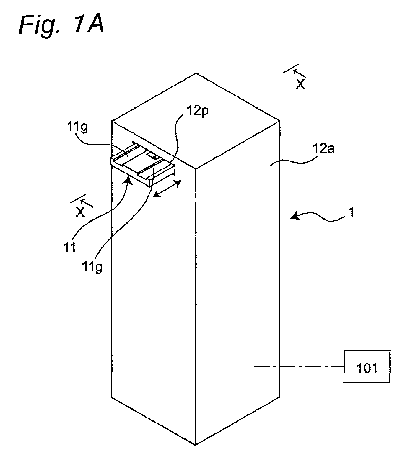
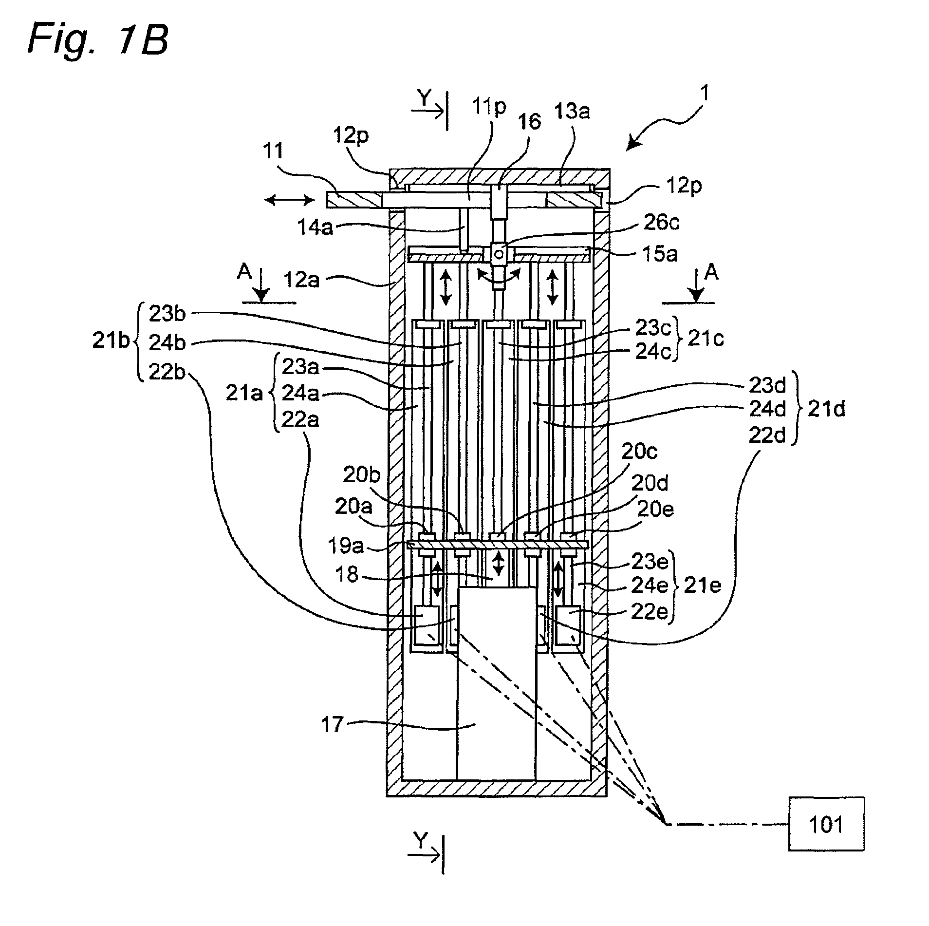
[0084]FIG. 1A is a perspective view schematically showing a translation actuator 1 serving as one example of a flexible actuator in accordance with a first embodiment of the present invention, FIG. 1B is a cross-sectional view taken along line X-X of FIG. 1A, and FIG. 1C is a cross-sectional view taken along line Y-Y of FIG. 1B. Moreover, FIG. 1E is a cross-sectional view taken along line A-A of FIG. 1B. In FIGS. 1A to 1C, a frame 12a which has an elongated rectangular parallelepiped box shape along a vertical direction serves as one example of a base member. A pair of guide rails 13a and 13b in parallel with each other are secured to the inside of the upper face of the frame 12a in such a manner as to extend in a lateral direction orthogonal to the vertical direction. A plate-shaped translation member 11 is connected to the guide rails 13a and 13b in such a manner as to freely move reciprocally in a lateral direction in FIG. 1B (to freely move rightward and leftward). The linear gu...

second embodiment

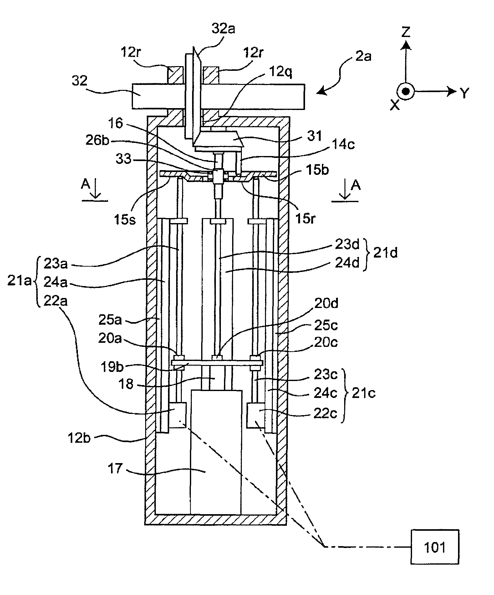
[0106]FIG. 2A is a cross-sectional view schematically showing a rotating actuator 2a serving as one example of a flexible actuator in accordance with a second embodiment of the present invention. FIG. 2B is a top view of the rotating actuator 2a, and FIG. 2C is a cross-sectional view taken along line A-A of FIG. 2A. FIG. 2F is an enlarged view showing the vicinity of a transmission plate 15b of FIG. 2A. The portions having the same functions as those of the above-described first embodiment are indicated by the same reference numerals, and overlapping description is not given. In the flexible actuator of the second embodiment, the Z-axis in the coordinate axes is defined as upward in the vertical direction. The X-axis is defined as a direction that is orthogonal to the Z-axis and penetrates one of side faces of a rectangular parallelepiped box-shaped frame 12b in the thickness direction, the frame 12b serving as one example of a base member. The Y-axis is defined as a direction that ...

third embodiment

[0124]FIG. 3A is a cross-sectional view schematically showing a rotating actuator 2b serving as one example of a flexible actuator in accordance with a third embodiment of the present invention. Moreover, FIG. 3B is a cross-sectional view taken along line A-A of FIG. 3A. The portions having the same functions as those of the second embodiment are indicated by the same reference numerals, and overlapping description is not given. In the flexible actuator of the third embodiment also, the Z-axis in the coordinate axes is defined as upward in the vertical direction. The X-axis is defined as a direction that is orthogonal to the Z-axis and penetrates one of side faces of a rectangular parallelepiped box-shaped frame 12c in the thickness direction, the frame 12c serving as one example of a base member. Moreover, the Y-axis is defined as a direction that is orthogonal to the Z-axis and X-axis and penetrates a side face that is orthogonally adjacent to the side face of the rectangular para...


PUM


Abstract

A displacement member can be displaced in a direction substantially perpendicular to a moving direction of a translation member that is held on a base member so as to reciprocatingly move thereon linearly, and an elastic mechanism secured to the base member accumulates and releases elastic energy in accordance with the distance to the displacement member. Protruding members of the translation member are pressed against a transmission member by generated force provided by the energy release from the elastic mechanism; thus, a distance adjusting operation between coupling mechanisms coupling the transmission member and the displacement member is controlled by a control device so that the relative position and relative angle between the displacement member and the transmission member are changed.

Description

TECHNICAL FIELD[0001]The present invention relates to a flexible actuator with which force control is easily carried out with superior operation efficiency, and a joint-driving unit using the actuator.BACKGROUND ART[0002]In recent years, there are high expectations for robots that are operated within areas close to people, such as robots for medical applications, domestic robots, and work support robots for use in factories. Unlike industrial robots, it is important for these robots to ensure safety when the robots are in contact with a person. In order to reduce impact upon contact, for the necessity to reduce a force to act on the contact point, the torque in the joint needs to be controlled to provide a flexible joint when viewed from the robot arm side. However, in the force (torque) control using an actuator for driving the joint, it is not possible to increase the response frequency infinitely, and in the case where force in a high-frequency range is exerted, such as in the ca...

Claims


Application Information

Patent Timeline
Patent Type & Authority Patents(United States)
IPC IPC(8): B25J17/00B25J17/02B25J18/00
CPCB25J17/00F16H21/54F16H23/10F16H33/02Y10T74/20335Y10T74/20329Y10T74/18832Y10T74/18992Y10T74/20305
Inventor ASAI, KATSUHIKO
Owner PANASONIC CORP
Why Eureka
Try Eureka