Integral nail bar hanger for recessed luminaire

a technology for recessed luminaires and nail bars, applied in the field of bar hangers, can solve the problems of limiting the ability to adjust the position of the bar hanger and luminaire, affecting the stability of the fixture, and permanently deforming the wood and the nailer,

Active Publication Date: 2011-01-25
HUBBELL LIGHTING INC
View PDF27 Cites 75 Cited by
  • Summary
  • Abstract
  • Description
  • Claims
  • Application Information

AI Technical Summary

Problems solved by technology

Once the nailer is driven into the joists, the wood and the nailer are permanently deformed and are not easily removed.
This limits the ability to adjust the position of the bar hanger and luminaire once attached to the ceiling joist.

Method used


Image

  • Integral nail bar hanger for recessed luminaire
  • Integral nail bar hanger for recessed luminaire
  • Integral nail bar hanger for recessed luminaire

Examples


second embodiment

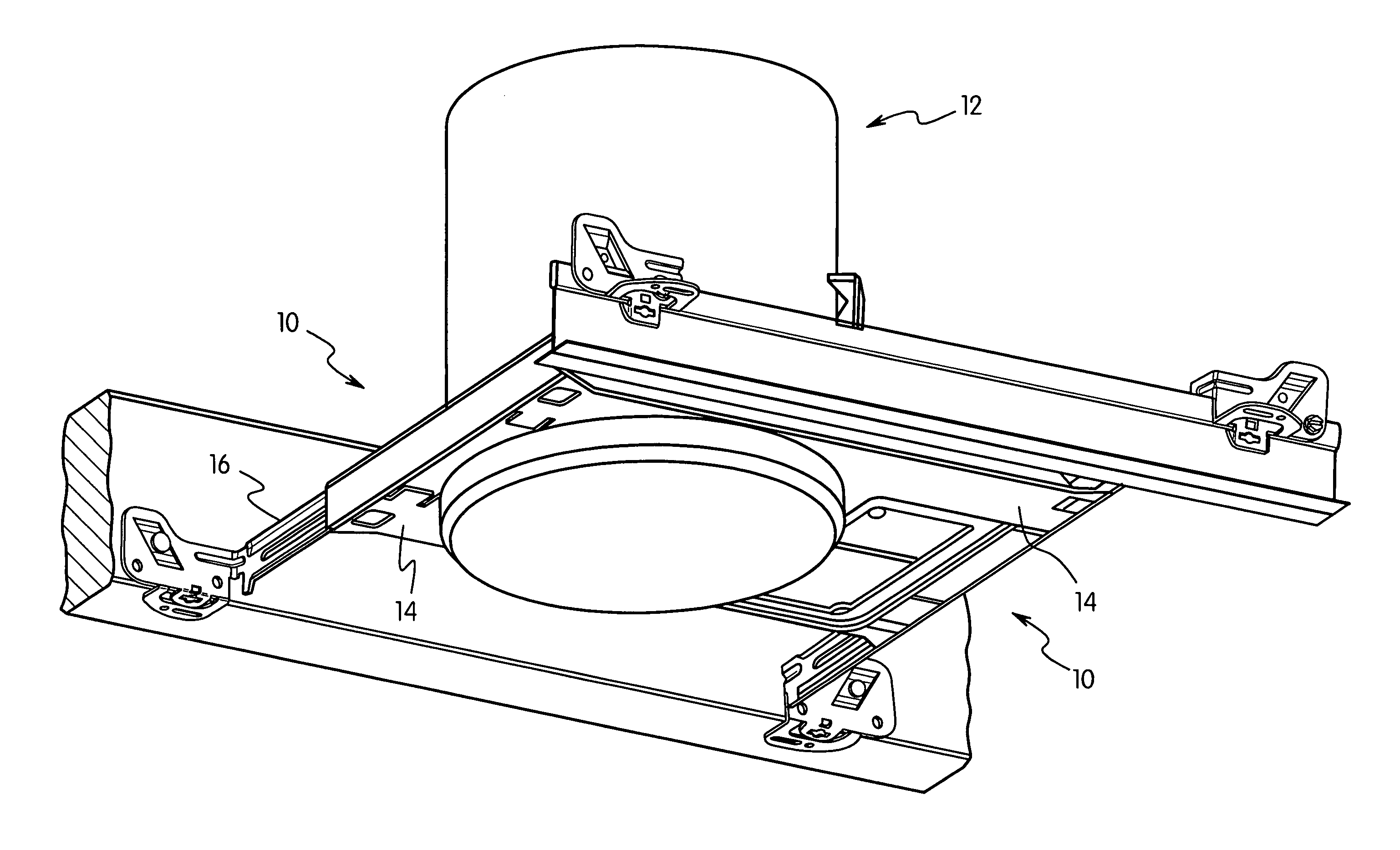
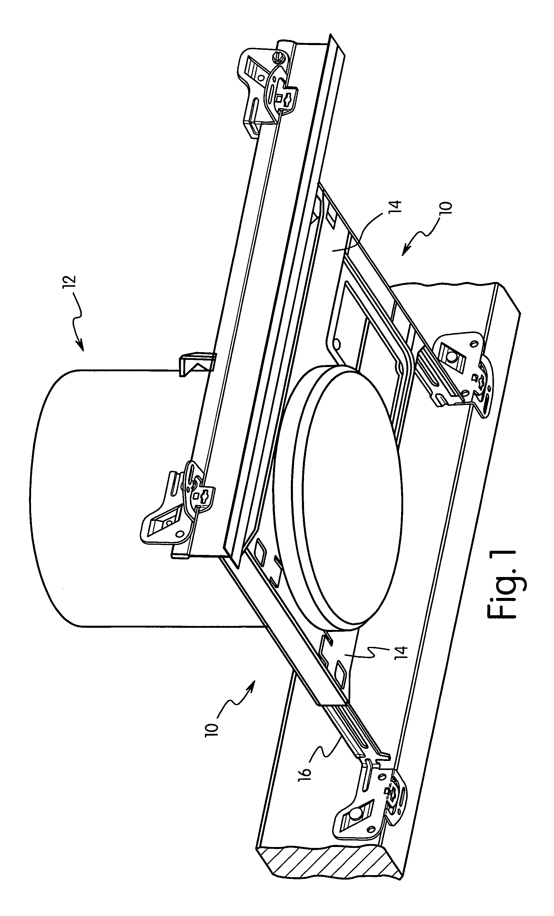
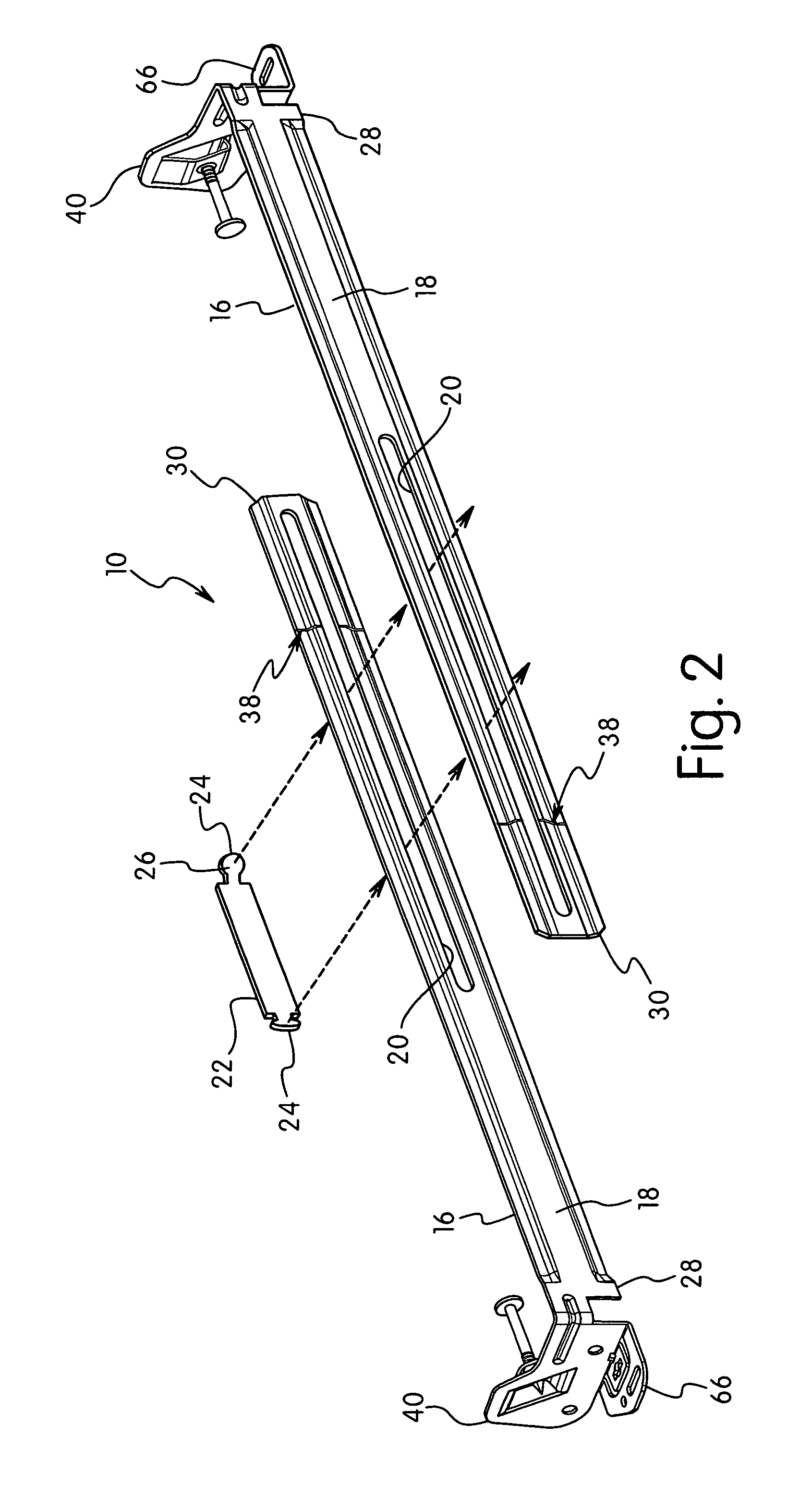
[0059]the invention is shown inFIGS. 12-15. The bar hanger 112 is similar to the previous embodiment and includes support arms 114 coupled together for sliding movement, a mounting plate 116 coupled to a first end of the respective support arm 114 and an attachment member 118.

[0060]Attachment member 118 has a substantially planar configuration extending perpendicular to the plane of the respective support arm 114. A bridge 120 is formed to capture a fastener 122 for attaching bar hanger to a ceiling joist as in the previous embodiment. In the previous embodiment, the length of the bar hanger 112 can be shortened only by the length of the respective support arms since the ends of the support arms contact the mounting plate. A removable tab is provided which can be removed in the field to allow the support arm or channel to pass beyond the mounting plate. In the embodiment shown in FIG. 13, mounting plate 116 includes a first vertical slot 124 and a second horizontal slot 126 adjacent...

third embodiment

[0063]the invention is shown in FIGS. 16-24. As in the previous embodiments, bar hanger 160 is adaptable for use in attaching to a ceiling joist or to a T-bar ceiling support. Bar hanger 160 includes support arms 162 having a longitudinal dimension with a first end 164 coupled to a mounting plate 166. Support arm 162 includes a notch 168 along a bottom edge 170 adjacent mounting plate 166 for receiving a T-bar.

[0064]Mounting plate 166 has a substantially planar configuration extending perpendicular to the plane of support arm 62 and includes a plurality of holes 172 for receiving fasteners to attach mounting plate 166 to a ceiling joist. A nailing bridge 174 for supporting a fastener is also provided as in the previous embodiments.

[0065]An attachment member 176 extends from a bottom edge 178 of mounting plate 166. Attachment member 176 has a substantially planar configuration and extends substantially perpendicular to the plane of mounting plate 166. Attachment member 176 is formed ...


PUM


Abstract

A bar hanger assembly is provided for supporting a recessed electrical device in a ceiling support. The bar hanger includes first and second telescoping support arms that are slidably connected together for adjusting the length of the bar hanger. The support arms having an elongated body with first and second ends and a mounting plate coupled to the first end. The mounting plate is oriented substantially perpendicular to the plane of the body. An attachment member is coupled to a bottom edge of the mounting plate for attaching to the bottom edge of a ceiling joist. The attachment member includes a detent extending from one side thereof. The attachment member can be bent from a first position perpendicular to the mounting plate to a second position parallel to the mounting plate for attaching to a T-bar support.

Description

CROSS-REFERENCE TO RELATED APPLICATION[0001]This application claims the benefit of provisional application Ser. No. 60 / 722,004, filed Sep. 30, 2005, which is hereby incorporated by reference in its entirety.FIELD OF THE INVENTION[0002]The present invention is directed to a bar hanger for supporting a recessed luminaire and lighting fixture to ceiling joists and to a T-bar support of a suspended ceiling. The invention is particularly directed to a bar hanger that can be adapted for mounting to either a ceiling joist or to a T-bar support of a suspended ceiling.BACKGROUND OF THE INVENTION[0003]Recessed luminaires and lighting fixtures for installation in wood construction typically include bar hangers that are coupled to the luminaire and including mounting ends for attachment to adjacent ceiling joists. Bar hangers commonly include a barbed or hooked nailer that is integrally formed from the bar hanger material blank. The bar hanger head is placed against the joist and a hammer is us...

Claims


Application Information

Patent Timeline
Patent Type & Authority Patents(United States)
IPC IPC(8): F16M13/00
CPCF04D25/088Y10S248/906
Inventor WRIGHT, CRAIG D.NEWBOLD, RONALD C.PRIMOUS, CHRISTOPHER C.GEORGE, CLYDE W.
Owner HUBBELL LIGHTING INC
Why Eureka
Try Eureka