Converter with position adjustable plug

a technology of plug and plug socket, which is applied in the field of converters, can solve the problems of fixed connection direction between the plug and the casing of the conventional converter, inconvenient use, and inability to adjust or change,

Inactive Publication Date: 2011-01-25
BUFFALO CORP LTD
View PDF5 Cites 15 Cited by
  • Summary
  • Abstract
  • Description
  • Claims
  • Application Information

AI Technical Summary

Benefits of technology

[0007]The main objective of the present invention is to provide a converter that can adjust the direction of a plug relative to a casing of the converter.

Problems solved by technology

However, the connection direction between the plug and the casing of the conventional converter is fixed and cannot be adjusted or changed.
When the conventional converter is interfered with the object or the structure that mounted around the power outlet and the plug of the conventional converter cannot mount with the power outlet and this is inconvenient in use.

Method used


Image

  • Converter with position adjustable plug
  • Converter with position adjustable plug
  • Converter with position adjustable plug

Examples


Embodiment Construction

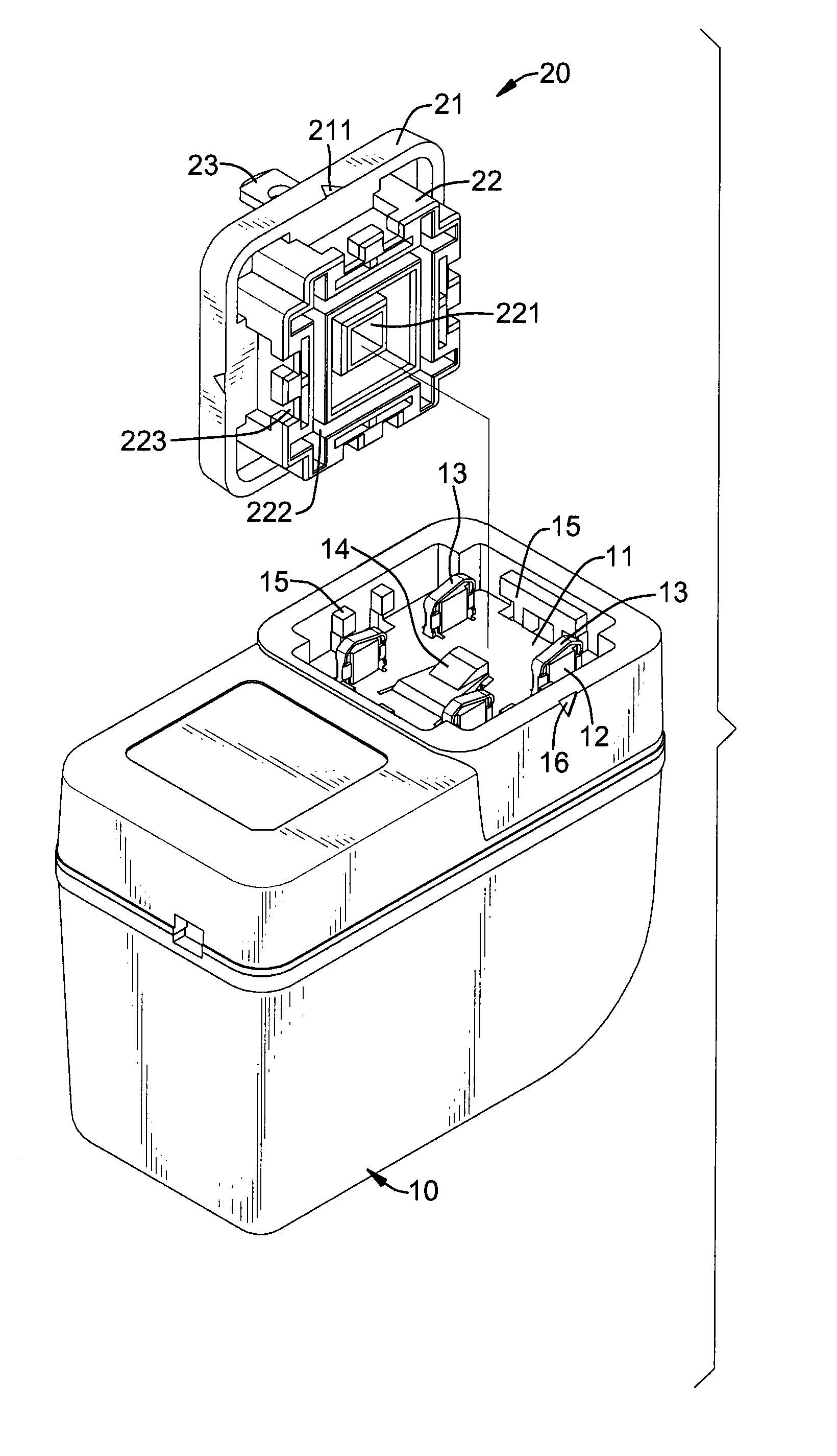
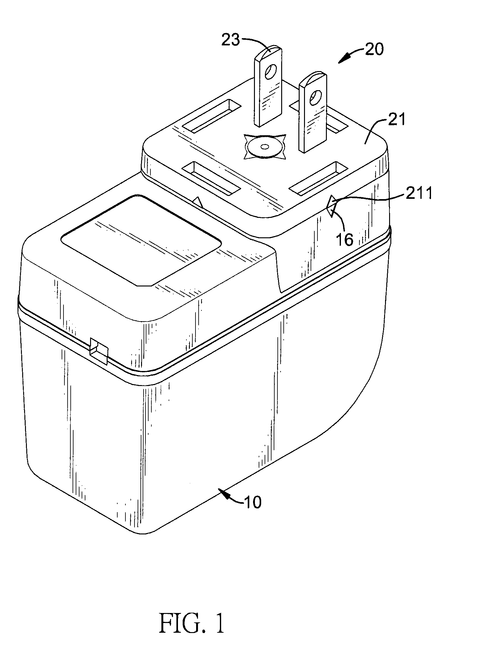
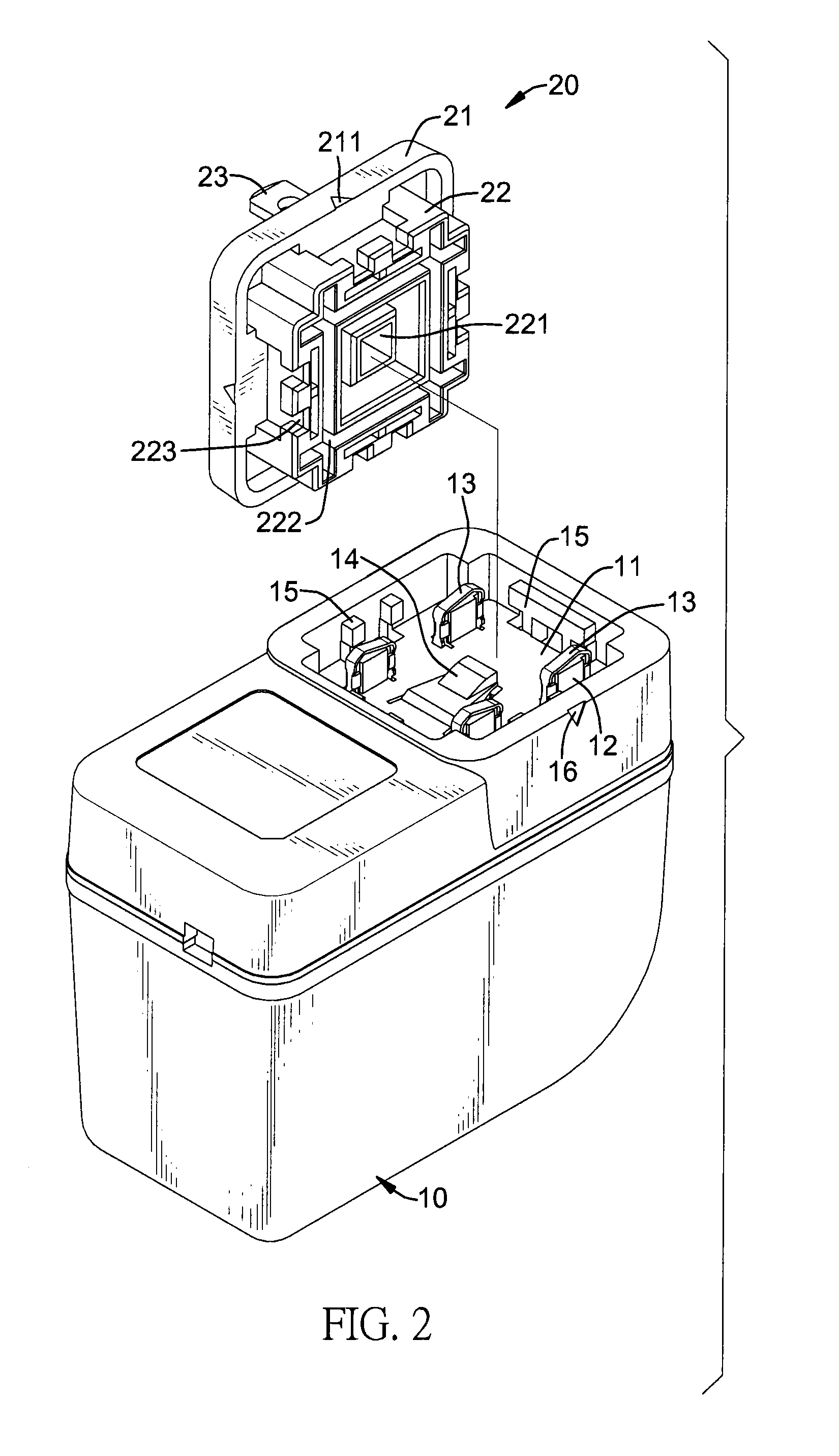
[0015]With reference to FIGS. 1 and 2, a converter in accordance with the present invention comprises a casing (10) and a plug (20).

[0016]The casing (10) has a connection side, an external surface, a mounting recess (11), multiple position posts (12), multiple conductive slices (13), an engaging tab (14), multiple mounting protrusions (15) and multiple datum marks (16).

[0017]The mounting recess (11) is formed in the connection side of the casing (10) and has a bottom, an annular sidewall and a center.

[0018]The position posts (12) are formed on and protrude from the bottom of the mounting recess (11) around the center of the mounting recess (11) and each position post (12) has an external surface, and may be four position posts (12) formed on and protrude from the bottom of the mounting recess (11), and each pair of adjacent position posts (12) have a specified distance.

[0019]The conductive slices (13) are mounted around the position posts (12) and connected to the bottom of the moun...


PUM


Abstract

A converter has a casing and a plug. The casing has a mounting recess, multiple position posts, multiple conductive slices and multiple mounting protrusions. The mounting recess is formed in the casing. The position posts are formed on and protrude from the mounting recess. The conductive slices are mounted around the position posts. The mounting protrusions are formed on the mounting recess. The plug is detachably mounted on the casing and has an escutcheon, an engaging protrusion and multiple terminals. The escutcheon covers the mounting recess. The engaging protrusion is formed on the escutcheon, is mounted in the mounting recess and has a position groove and multiple holding grooves. The position is annular formed in the engaging protrusion and is mounted around the position posts. The holding grooves are formed on the engaging protrusion and engage the mounting protrusions. The terminals are formed on the escutcheon.

Description

BACKGROUND OF THE INVENTION[0001]1. Field of the Invention[0002]The present invention relates to a converter, and more particularly to a converter that can adjust the direction of a plug relative to a casing of the converter.[0003]2. Description of Related Art[0004]A conventional converter is used to transform and rectify voltage of a power source and has a casing and a plug. The casing has an interior, a conversion module, a connection surface and a mounting recess. The conversion module is mounted in the interior of the casing. The mounting recess is formed in the connection surface of the casing. The plug is detachably mounted in casing, selectively mounted in the power source and has a connection surface and a mounting panel. The mounting panel is formed on and protrudes from the connection surface of the plug and is detachably mounted in the mounting recess of the casing.[0005]Although, the plug can be detachably connected to the casing of the conventional converter by the moun...

Claims


Application Information

Patent Timeline
Patent Type & Authority Patents(United States)
IPC IPC(8): H01R29/00
CPCH01R13/514H01R13/6675H01R31/06H01R27/00
Inventor CHIANG, YUNG-HSUOZAKI, HIROSHI
Owner BUFFALO CORP LTD
Why Eureka
Try Eureka