Systems and methods for monitoring a saw blade during sawing

a technology of monitoring system and saw blade, applied in the field of saw blades, can solve the problems of insufficient information provided by current feedback system to control this evolving process, and the less valuable mix of lumber

Active Publication Date: 2011-02-15
WEYERHAEUSER NR CO
View PDF28 Cites 7 Cited by
  • Summary
  • Abstract
  • Description
  • Claims
  • Application Information

AI Technical Summary

Benefits of technology

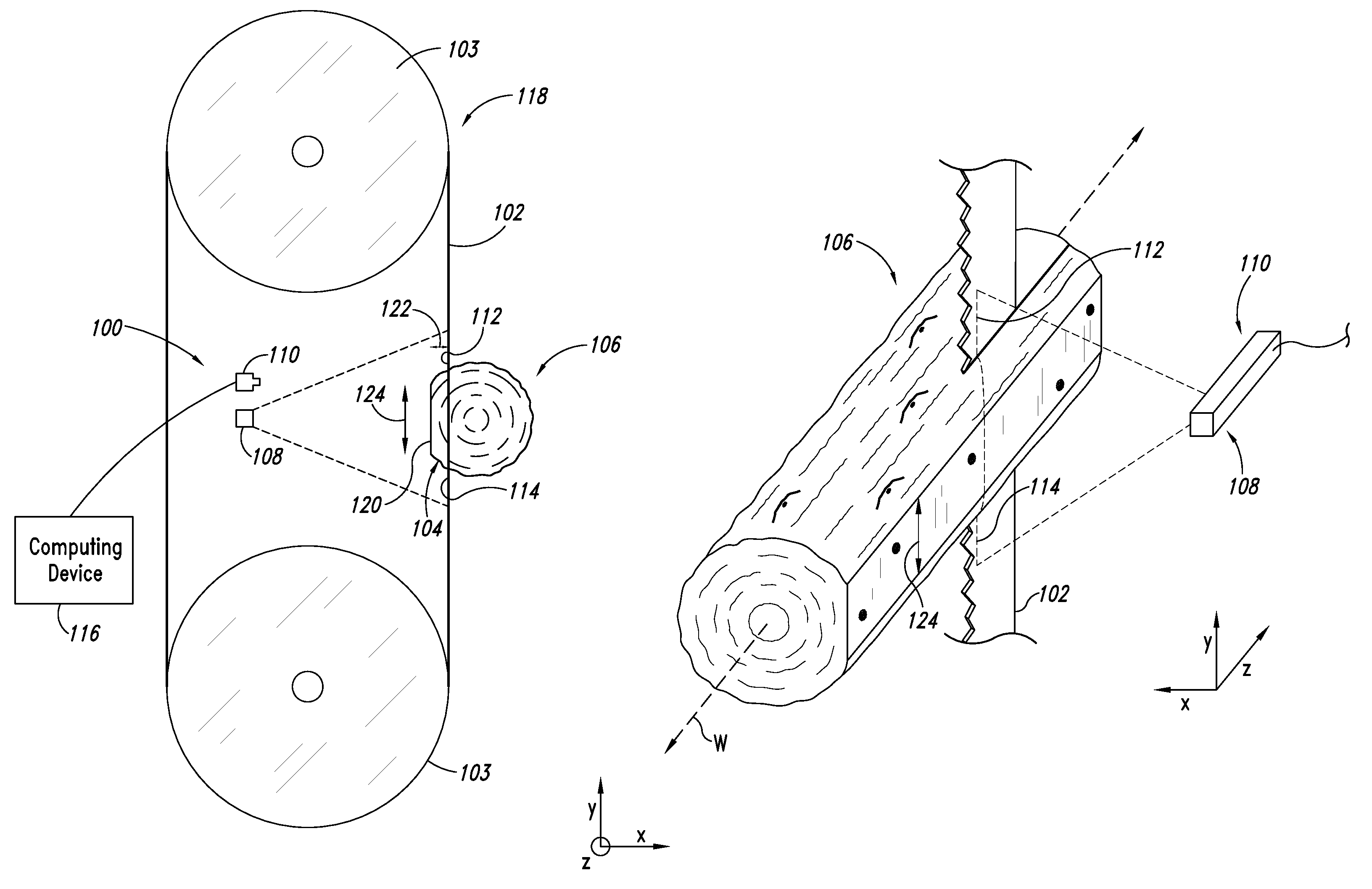
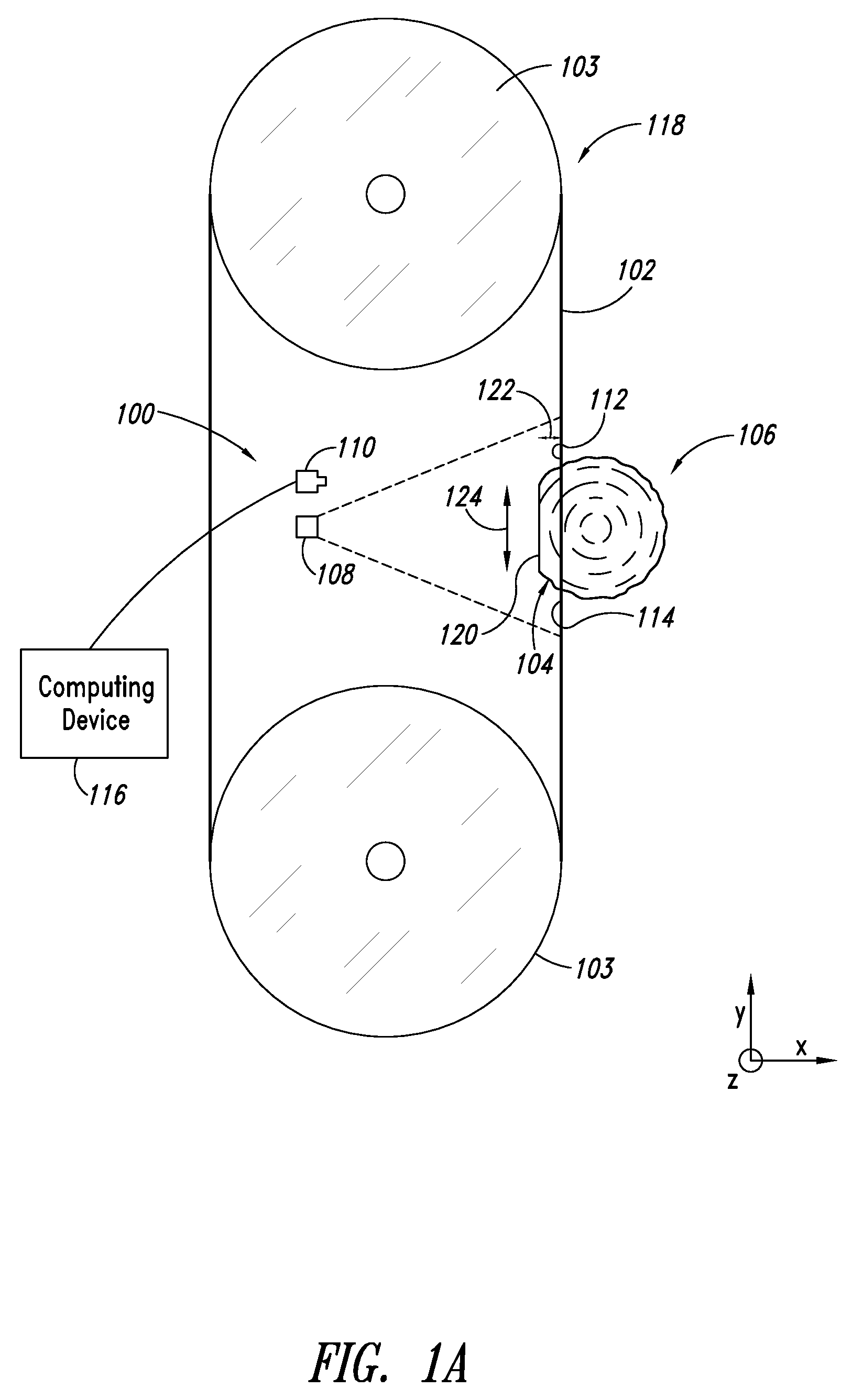
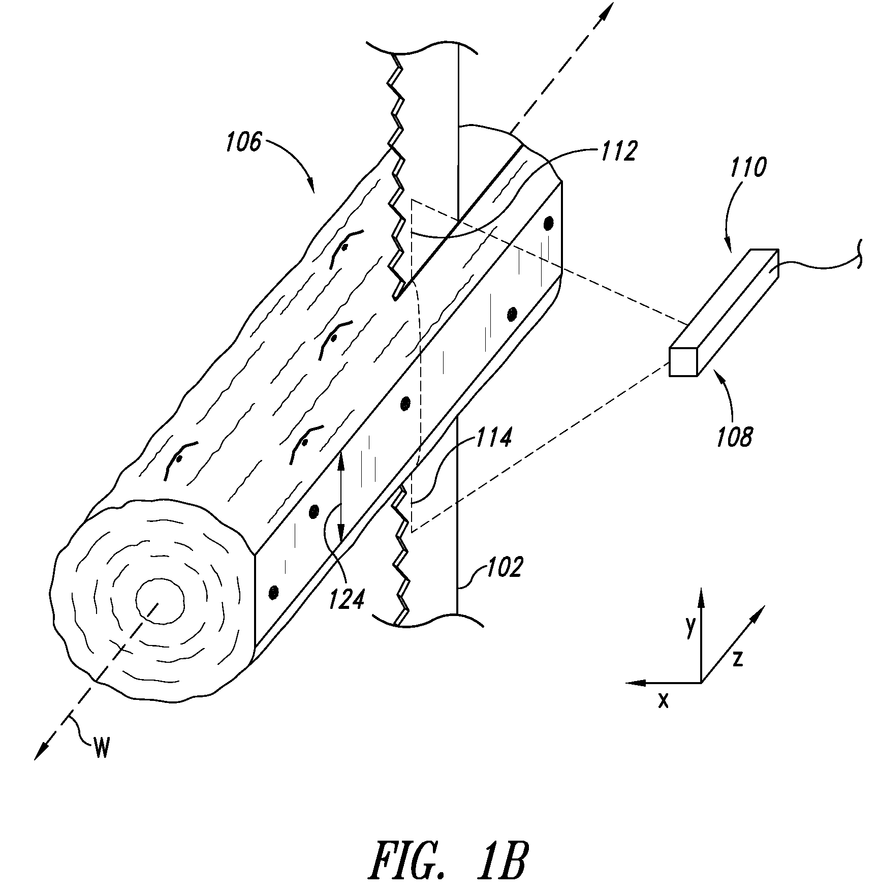
[0008]An automatic feedback system that can provide many of the above advantages is described below. The feedback system includes a planar laser scanner located near a saw blade. As a log segment (for example) is sawn by the saw blade, the laser scanner scans both the saw blade as well as the sawn portion of the log segment. With the laser scanner positioned to scan where the saw blade enters and exits the log segment, the feedback system can detect deflection in the saw blade anywhere along the length of the log segment. By scanning the log segment as well, the feedback system can detect the geometry of the sawn portion of the log segment along its entire length and can also determine the width of the new face of the log segment created by the sawing process.
[0009]To further improve the capabilities of the feedback system, the planar laser scanner may include a second laser upstream from the saw blade. The second laser can be positioned to scan the log segment right before sawing and can detect if last minute adjustments need to be made to properly position the log segment relative to the saw blade. The second laser can also be used to scan the log segment as the log segment is transported back to the starting point for a next pass to determine whether or not there are knots or other imperfections in the new face of the log segment that might necessitate a reevaluation of the optimal mix of lumber.

Problems solved by technology

These machines produce lumber from each log segment, often without any human intervention.
Yet, current feedback systems do not provide enough information to control this evolving process.
For example, although the initial optimal mix of lumber based on the geometry of the log segment surface may have been 3 2″×10″ boards, knots hidden within the log segment may make this mix of lumber less valuable.

Method used


Image

  • Systems and methods for monitoring a saw blade during sawing
  • Systems and methods for monitoring a saw blade during sawing
  • Systems and methods for monitoring a saw blade during sawing

Examples


Embodiment Construction

[0023]In the following description, certain specific details are set forth in order to provide a thorough understanding of various disclosed embodiments. However, one skilled in the relevant art will recognize that embodiments may be practiced without one or more of these specific details, or with other methods, components, materials, etc. In other instances, well-known structures associated with computing devices, illumination and imaging systems and / or saws have not been shown or described in detail to avoid unnecessarily obscuring descriptions of the embodiments.

[0024]Unless the context requires otherwise, throughout the specification and claims which follow, the word “comprise” and variations thereof, such as, “comprises” and “comprising” are to be construed in an open, inclusive sense, that is, as “including, but not limited to.”

[0025]Reference throughout this specification to “one embodiment” or “an embodiment” means that a particular feature, structure or characteristic descr...


PUM

PropertyMeasurementUnit
movementaaaaaaaaaa
brightnessaaaaaaaaaa
thicknessaaaaaaaaaa

Abstract

A light source is used to illuminate a sawn portion of a piece of wood and exposed surfaces of the saw blade on both sides of the sawn portion. The sawn portion and the exposed surfaces of the saw blade are then imaged substantially concurrently using a single image generator. At least one geometric characteristic of the sawn portion and at least one geometric characteristic of the saw blade are determined based on the imaging.

Description

BACKGROUND[0001]1. Technical Field[0002]This description generally relates to saw blades, and more particularly to monitoring saw blades during sawing.[0003]2. Description of the Related Art[0004]The sawmill industry has become largely automated. Full length tree trunks are delivered to sawmills, where they are automatically debarked, scanned and cut into log segments based on their scanned geometry. These log segments are then typically processed by a number of automated machines, depending on the sawmill and the type of wood. These machines produce lumber from each log segment, often without any human intervention.[0005]In some sawmills, for example, each log segment is scanned, and a computer optimizer determines an optimal mix of lumber that can be obtained from that log segment based on its scanned geometry. For example, the computer optimizer may determine that a given log segment can be processed to obtain 3 2″×10″ boards, which represents the highest current market value obt...

Claims


Application Information

Patent Timeline
Patent Type & Authority Patents(United States)
IPC IPC(8): G05B19/18B27B1/00B23Q15/00
CPCB23Q17/20B23Q17/24B27B31/06G05B19/401G05B2219/37208G05B2219/37571G05B2219/37574G05B2219/50062G05B2219/45229Y10T83/145Y10T83/536
Inventor BARKER, EARL
Owner WEYERHAEUSER NR CO
Why Eureka
Try Eureka