System for guiding a vehicle along at least one guiding rail

a technology of guiding rails and guiding rails, applied in the field of systems, can solve problems such as wear and tear of rails and rollers

Inactive Publication Date: 2011-02-22
SOC EURO DINGENIERIE MECANIQUE EURODIM SA
View PDF24 Cites 7 Cited by
  • Summary
  • Abstract
  • Description
  • Claims
  • Application Information

AI Technical Summary

Benefits of technology

[0019]According to yet another characteristic of the invention, the system has two rollers, each of which has a radial external part intended for coming into contact with a side surface of the head of the rail and a radial internal part intended for coming into contact with the upper surface of the rail head, and one of the rollers has a peripheral ring intended for coming into contact with an annular surface of the other roller so as to ensure the rotation of the roller by friction with the roller.

Problems solved by technology

This known guiding system has the disadvantage that the contact of the side surfaces of the flanges forming the cheeks with the surfaces of the rail head facing them involves friction between the surfaces in contact and thus wear and tear on both the rail and the roller.

Method used


Image

  • System for guiding a vehicle along at least one guiding rail
  • System for guiding a vehicle along at least one guiding rail
  • System for guiding a vehicle along at least one guiding rail

Examples


first embodiment

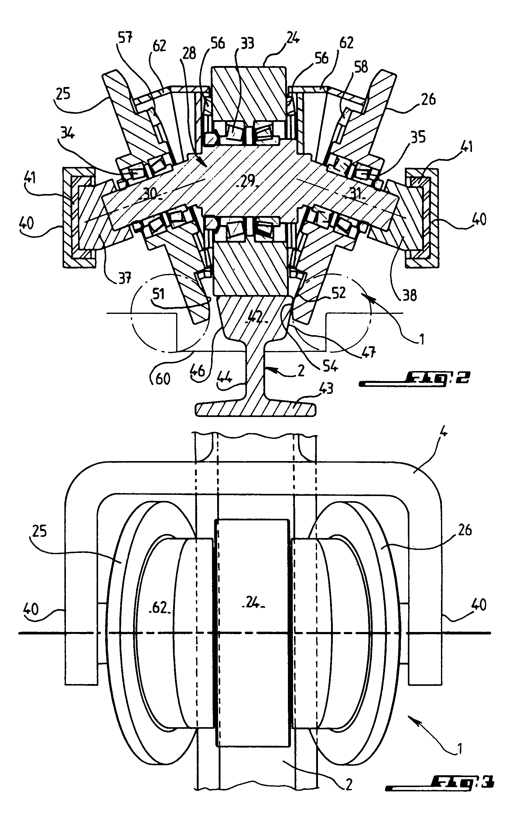
[0041]FIG. 2 shows a first variation of roller device 1 according to the invention. This device has three separate rollers, namely central roller 24 and two side rollers 25 and 26 on either side of it. The three rollers are mounted so as to rotate on crankshaft 28 produced as a single piece, which has central part 29 for support of central roller 24 and a part on the right and on the left, respectively 30 and 31. Parts 30 and 31 are inclined relative to the axis of central part 29 so that rollers 25 and 26 are inclined, relative to central roller 24, towards one another at the site of rail 2. Rollers 24, 25, 26 are mounted on their shaft parts, 29, 30 and 31, respectively, via rolling bearings, 33, 34, 35 respectively. Inclined shaft parts 30, 31 are held in support parts 37, 38 engaged in limbs 40 of fork 4, with insertion of elastomer layer 40, 41.

[0042]Rail 2 in the example represented has head 42 as a part connected to base 43 by narrower intermediate part 44. Head 42 of the rai...

third embodiment

[0054]FIG. 8 illustrates roller device 1 according to the invention. This embodiment has in common with FIGS. 2 to 5 the fact that side rollers 25, 26 are inclined and independent rollers. This embodiment is distinguished from the first by the means for synchronization of the rotations of these side rollers, from central roller 24. The rotation of the side rollers by the central roller occurs by means of a device with belts and pulleys. The rotation of central roller 24 is transmitted by first belt 82 to pulley 83, which is rotationally connected with shaft 84 bearing two other pulleys 85, 86, which are also rotationally connected with shaft 84. Each of the two pulleys 85, 86 transmits the rotation of shaft 84 via belt 87, 88 to the corresponding side roller 25, 26. Return pulleys 89, 90 are provided so as to ensure the appropriate orientation of the belts at the site of the rollers.

[0055]FIG. 9 illustrates a possibility for performing the synchronization also by gearing of the incl...

fourth embodiment

[0056]FIG. 10 illustrates roller device 1 according to the invention, in two slightly different variations which are indicated on the left and on the right of the axis of symmetry of central roller 24.

[0057]In this embodiment, side rollers 25, 26 are independent of roller 24 but are mounted so as to rotate on shaft parts 30, 31, which are parallel to shaft part 28, for support of the central roller. This roller device is suitable for rolling on rail head 42 whose rolling surface is planar as in the case of FIG. 2. In contrast, the side surfaces by which the side rollers are intended to come into contact with the rail are inclined in the manner represented in FIG. 7 and therefore bear the references 77 and 78. So that the rotation speeds of the rollers at points of contact 54 with rail head 42 can be identical to the rotation speed at the site of peripheral rolling surface 49 of central roller 24, on one hand, and so that the rotational synchronization of side rollers 25, 26 on centr...


PUM


Abstract

A system for guiding a vehicle along a guiding rail includes a guide roller device, with at least one rolling bearing roller and at least one lateral roller having a diameter and shape contacting the rail so that the lateral roller has the same speed at a point of contact with the rail as the central bearing roller on a rolling surface on the rail. The system can be used for tramways.

Description

[0001]The invention relates to a system for guiding a vehicle along at least one guiding rail, having a rolling surface and at least one side surface of which constitutes a guiding surface, of the type which has a guiding roller device configured to cooperate with the rolling surface and the side surface and having a rolling bearing part intended for being in rolling contact by its peripheral surface with the upper rolling surface of the rail and at least one side part capable of coming into contact with the side surface of the rail facing it.BACKGROUND[0002]Systems of this type are already known. These systems are suitable for cooperating with one or two rails, and their roller device has a rolling bearing surface and at least one side part in the form of a flange which is rotationally connected with the bearing part, projects radially towards the exterior, and comes in contact with the guiding surface of the rail.[0003]This known guiding system has the disadvantage that the contac...

Claims


Application Information

Patent Timeline
Patent Type & Authority Patents(United States)
IPC IPC(8): B61F1/00B61F9/00B62D1/26
CPCB61F9/00B62D1/265
Inventor DUPONT, BERNARDBOULAT, LUOFORGET, REMI
Owner SOC EURO DINGENIERIE MECANIQUE EURODIM SA
Why Eureka
Try Eureka