Convertible C-clamp

a c-clamp, portable technology, applied in the direction of candle holders, building scaffolds, lighting supports, etc., can solve the problems of limited display space on the control panel of an aircraft, limited number of instruments displayed on the control panel, and limit the number of instruments available on the control panel of any aircra

Active Publication Date: 2011-02-22
CARNEVALI JEFFREY D
View PDF40 Cites 83 Cited by
  • Summary
  • Abstract
  • Description
  • Claims
  • Application Information

AI Technical Summary

Benefits of technology

[0015]According to another aspect of the novel convertible C-clamp device, the novel convertible C-clamp device includes a second arched movable clamping jaw that is interchangeable with the first planar movable clamping jaw on the convex swivel head of the threaded rod. The second arched movable clamping jaw includes an arched forward clamping surface and an aperture rearward thereof that communicates with a complementary concave socket formed therein, wherein the aperture is sized to releasably receive the convex swivel head of the threaded rod therethrough into the complementary concave socket, and wherein the complementary concave socket is formed to freely rotate and swivel about the convex swivel head.

Problems solved by technology

Display space on the control panel of an aircraft is limited by the physical dimensions of the cockpit and the number of instruments displayed on the control panel is limited by the physical size of the instrument's display which must be large enough to be easily read by the crew.
These control panel space constraints limit the number of instruments available on the control panel of any aircraft, from the small private airplane to the large commercial airliners.
Although larger and carrying more instruments, commercial airliners suffer similar space constraints.
Similar constraints also limit the number of instruments which can be displayed on the control panel of a land or water-based vehicle, i.e., the dash board of an automobile or a boat.
Because display space is a premium, instrument panels generally do not provide space for redundancy, i.e., back-up displays for any or all flight critical instruments.
Nor is space available for additional flight information.
However, the pilot is forced to continually look down at the lap board to read the documents which interrupts attention to the instruments and windshield.
However, while pilots need to comfortably and effectively consult these documents in a timely fashion as the need arises, such maps and documents tend to obscure other critical flight instruments and engine and fuel monitoring instruments on the control panel.
Also, these documents tend to become awkward and unwieldy when too large to conveniently fit on the clip board.
Some further disadvantages of control column mounted clip boards are that they are costly for many private pilots and that small aircraft manufacturers cannot provide these useful displays because their temporary nature does not allow for certification.
However, suction cup clamp devices may have limited value in mounting electronics devices as, under certain circumstances, ambient light tends to wash out images on display screens, especially liquid crystal display (LCD) screens.
Thus, to date, whether an air, land or water-based vehicle, cockpit display space remains severely limited.

Method used


Image

  • Convertible C-clamp
  • Convertible C-clamp
  • Convertible C-clamp

Examples


Embodiment Construction

[0052]In the Figures, like numerals indicate like elements.

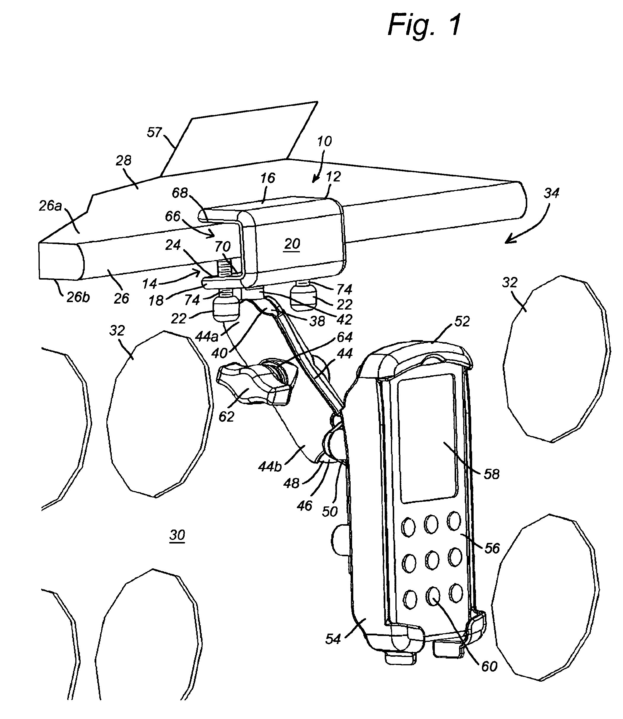
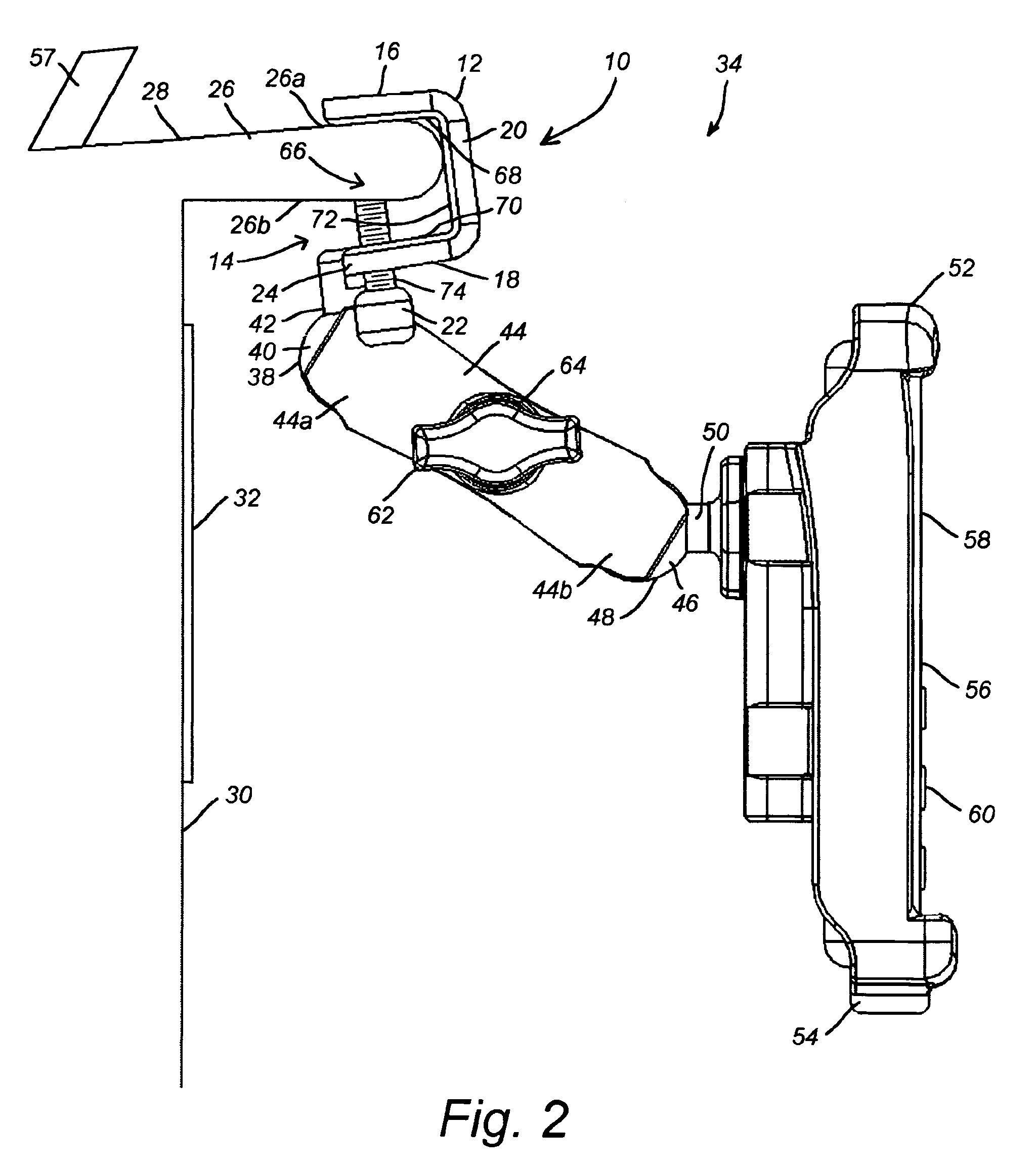
[0053]FIG. 1 is a perspective view showing an example of a method of operating a novel clamp device 10 of the type disclosed herein. The clamp device 10 is formed of a substantially rigid elongated jaw portion 12 forming an elongated and substantially uniform mouth opening 14 thereinto between opposing upper and lower plates 16 and 18 spaced apart by an opposing backing plate portion 20. The upper and lower plates 16, 18 and backing plate 20 are illustrated here by example and without limitation as substantially identical uniformly long, flat and relatively thin rigid plates. The backing plate 20 is optionally a thicker plate than the upper and lower plates 16, 18 and may be curved, without deviating from the scope and intent of the present invention. A pair of thumb screws 22 is spaced apart along the elongated jaw portion 12. The thumb screws 22 are threaded into the mouth opening 14 adjacent to an outer lip portion 24 of ...


PUM


Abstract

A convertible clamp device including a C-shaped frame having first and second substantially opposing interconnected arms; a clamping rod carried by the first arm for longitudinal movement in a first clamping direction toward an internal face of the second arm and in a second opposite direction away from the second arm; different first and second movable clamping jaws removably coupleable to a portion of the clamping rod between the arms of the frame; and different first and second stationary clamping anvils being disposable on the internal face of the second arm.

Description

[0001]This application is a Continuation-in-part and claims priority benefit of copending parent U.S. patent application Ser. No. 11 / 809,281 filed in the name of Jeffrey D. Carnevali on May 31, 2007, the complete disclosure of which is incorporated herein by reference.FIELD OF THE INVENTION[0002]The present invention relates generally to clamps for holding portable devices, and in particular to portable C-clamps for use with ball-and-socket connectors in aviation environments having both cylindrical and rectilinear mounting surfaces.BACKGROUND OF THE INVENTION[0003]Display space on the control panel of an aircraft is limited by the physical dimensions of the cockpit and the number of instruments displayed on the control panel is limited by the physical size of the instrument's display which must be large enough to be easily read by the crew. These control panel space constraints limit the number of instruments available on the control panel of any aircraft, from the small private ai...

Claims


Application Information

Patent Timeline
Patent Type & Authority Patents(United States)
IPC IPC(8): A47B96/06E04G3/00F16B1/00G09F7/18
CPCA47B21/0314F16B2/065F16M11/041F16M11/14F16M11/2078F16M13/00F16M13/022B60R11/02F16M2200/022B60R11/0241B60R11/0252B60R11/0258B60R2011/0059B60R2011/0089B64D2045/0075
Inventor CARNEVALI, JEFFREY D.
Owner CARNEVALI JEFFREY D
Why Eureka
Try Eureka