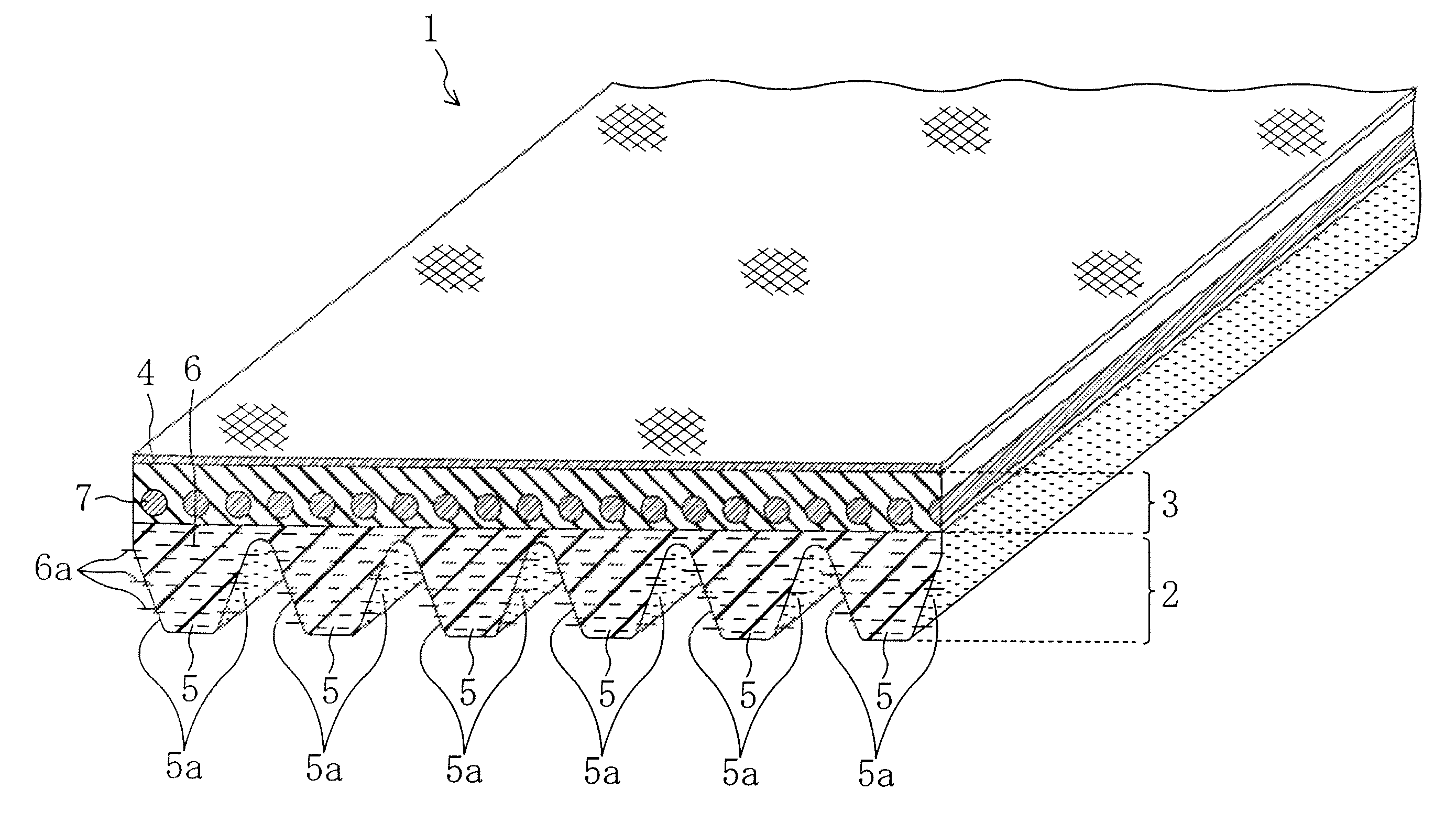
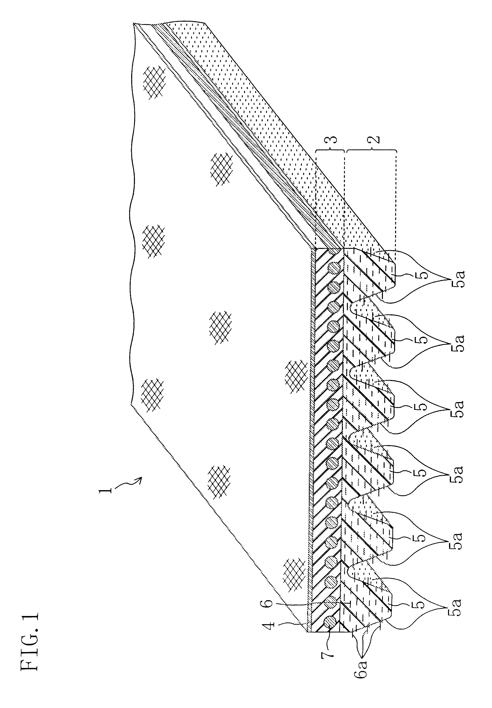
[0009]The present invention has been made in view of the foregoing and has its object of providing a V-ribbed belt for transmitting frictional force by being in contact with a V groove of a driven pulley, which keeps the apparent coefficient of dynamic friction of the side faces of rubber ribs against a V grooved face of the pulley low in normal driving operation while increasing the apparent coefficient of dynamic friction earlier after the belt starts slipping (after belt slip) due to locking of the driven pulley by providing a scheme to the rubber ribs of the V-ribbed belt. In other words, the object is to provide a V-ribbed belt capable of suppressing noise generation by keeping the apparent coefficient of dynamic friction low in normal driving operation and of preventing belt breakage by allowing a torque limiter mechanism for the driven pulley to operate earlier and definitely after belt slip.
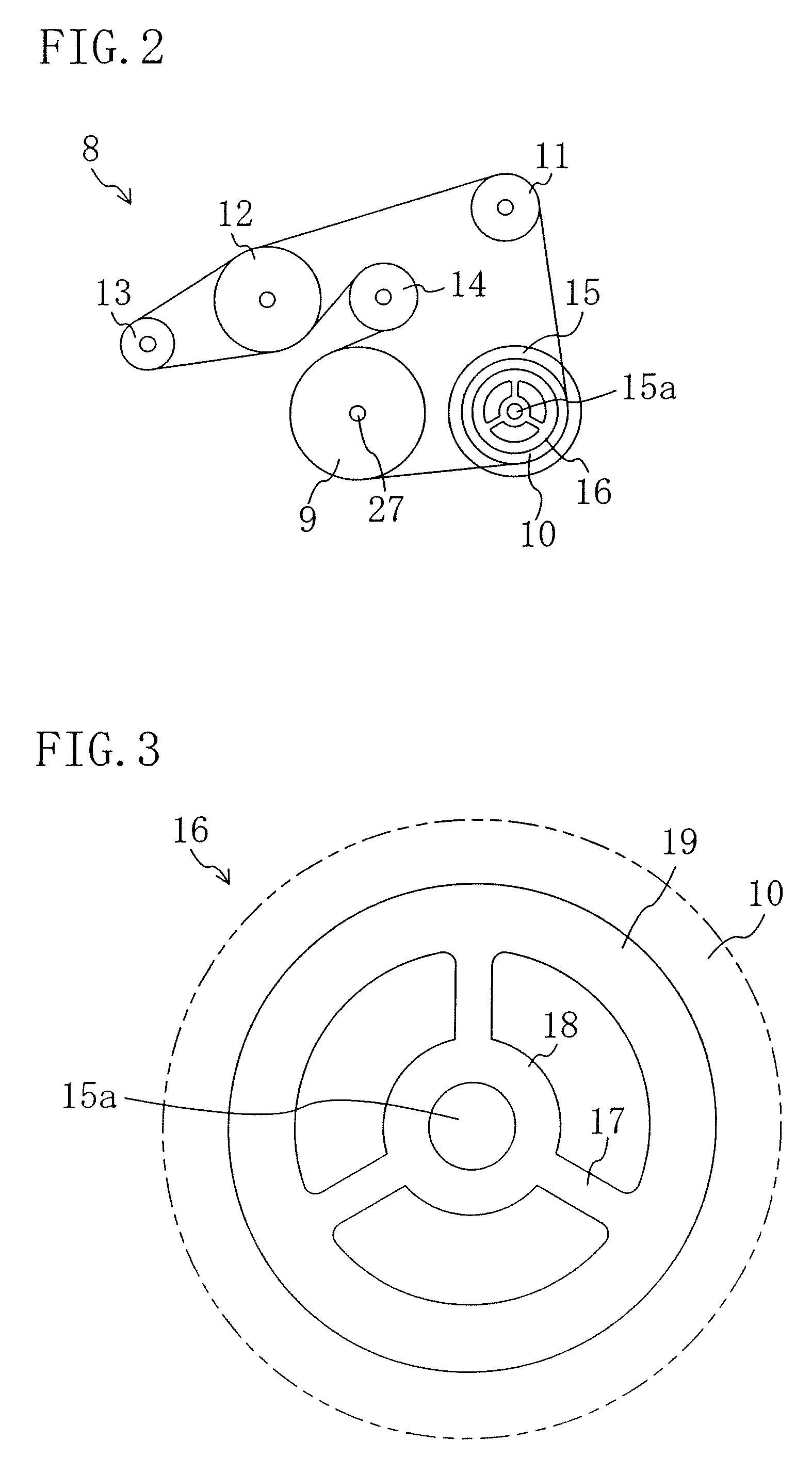
[0013]With the above arrangement, the apparent coefficient of dynamic friction can be kept low before belt slip and increases high after belt slip. Specifically, decrease in the number of the short fibers protruded from the side faces of the rubber ribs after belt slip increases the contact area between the side faces of the rubber ribs and the V groove face of the driven pulley earlier to increase the apparent coefficient of dynamic friction. For example, in the case where the belt is applied to a DL pulley for driving an A / C compressor including a torque limiter mechanism, an increase in apparent coefficient of dynamic friction increases the torque in the peripheral direction working on the DL pulley to allow the torque limiter mechanism to operate early and definitely. This causes the DL pulley to idle to suppress frictional heat generated due to slip of the belt on the pulley. Hence, belt breakage caused due to the frictional heat can be prevented. Specifically, heat hardens the rubber of a belt to lower the flexibility, and accordingly, repetitive bending and stretching by rotations leads to formation of a crack in the belt. The core cords of the belt contribute to almost all part of the belt strength. Accordingly, though such a crack less lowers the belt strength, the crack will develop to the adhesion layer and spread in the peripheral direction to lead to transmission failure and damage by exposure of a core cord, thereby leading to belt breakage. The present invention provides means for solving these problems.
[0015]In the above arrangement, the apparent coefficient of dynamic friction after belt slip is increased double or more of that before belt slip, so that the torque limiter mechanism operates definitely when applied to a DL pulley, for example. In setting a predetermined torque value of the DL pulley, a sufficient margin can be set for the torque in the peripheral direction (strictly, a maximum value of the torque in the peripheral direction) working on the DL pulley before slip, that is, in normal driving operation, thereby preventing mis-operation. If an increasing rate of the apparent coefficient of dynamic friction is small, a sufficient margin cannot be set in setting the predetermined torque value to involve the following problems. First, attachment of water, dust, or the like to the belt in normal driving operation may cause belt slip to invite an instant torque increase, of which torque increasing rate is smaller than that in the case where the driven pulley is locked fully. Even such a small torque increase, which is not critical to the belt or which does not lead to belt breakage), may cause the torque limiter mechanism to operate. Secondly, the predetermined torque value must be set small, which forces lowering of the breaking strength of the limiter portion, thereby lowering the fatigue resistance of the limiter portion to lower the durability of the torque limiter mechanism. The present invention provides means for solving the above problems.
[0017]With the above arrangement, the short fibers are softened or dissolved by heat generation after belt slip. Slip of the belt on the driven pulley applies shearing force to the short fibers, which have been softened, so that the short fibers can be cut readily. The dissolved short fibers fly readily. Namely, remaining protruded short fibers, which cannot have been buried by the operation of the first aspect, are cut or allowed to fly to decrease further the number of the protruded short fibers after belt slip.
[0025]In the above arrangement, the arithmetic average roughness (Ra) is set in the range between 1 μm and 3 μm, both inclusive, to allow the apparent coefficient of dynamic friction of the side faces of the rubber ribs to increase sharply after belt slip, thereby shortening a time period until the toque limiter mechanism starts operating. Specifically, decreases in the number of the short fibers after belt slip increases the contact area between the side faces of the rubber ribs and the V grove face of the driven pulley to increase influence of the arithmetic average roughness (Ra) of the rubber part at the side faces of the rubber ribs on the apparent coefficient of dynamic friction. Accordingly, the larger the arithmetic average roughness (Ra) of the rubber part of the rubber ribs is, the more sharply the apparent coefficient of dynamic friction increases after belt slip. When the arithmetic average roughness (Ra) is set equal to or smaller than 1 μm, the apparent coefficient of dynamic friction increases gently. In contrast, the arithmetic average roughness (Ra) is set equal to or larger than 3 μm, the apparent coefficient of dynamic friction in normal driving operation also increases to cause noise.
[0027]The above arrangement prevents the belt function from lowing caused due to heat generated at a slip face. Specifically, when nylon short fibers are softened by heat, rubber having less thermal resistance, such as chloroprene rubber (CR) or the like are carbonized to invite lowering of the belt function. Hence, ethylene propylene dien monomer (EPDM) is employed to increase the thermal resistance.


