Self-tightening traction assembly having tensioning device

a technology of tensioning device and traction assembly, which is applied in the direction of non-skid devices, snap fasteners, buckles, etc., to achieve the effect of reducing the size of the passageway and minimizing dirt and debris

Active Publication Date: 2011-03-08
PEERLESS CHAIN COMPANY
View PDF38 Cites 20 Cited by
  • Summary
  • Abstract
  • Description
  • Claims
  • Application Information

AI Technical Summary

Benefits of technology

[0006]It is an object of the present invention to provide a self-tightening snow chain having a tensioning device that more effectively tightens and provides easier installation. It is another object of the present invention to provide a tensioning device that can tighten a plurality of cords with one winding device, preferably a ratchet spool. It is yet another object of the present invention to provide a self-tightening snow chain having a tensioning device that is resistant to an infiltration of dirt, debris and moisture into the housing.
[0007]The present invention achieves these and other objectives by providing a tensioning device having two modes of operation. First, is an extended or extending mode that allows the user to extend the tensioning cord or cords from the housing and release their grip on the cord(s) without having the cord(s) wind-up into the housing. The ability to only allow movement in a wind-out direction is created when the ratchet spool is in a down position, where the spool, although biased in a wind-up direction, is blocked from turning in a wind-up direction. In one embodiment, in which the actuator includes an actuating lever and a cam lever, in order to position the ratchet spool in the down position, the user raises the actuating lever until the actuating lever is perpendicular to the housing and the cam lever pushes the ratchet spool down. In another embodiment, to position the ratchet spool in the down position, the user rotates a key within a key receiving opening in an actuator that includes a rotation disc that engages a cam disc such that the cam disc pushes the ratchet spool down. When the ratchet spool is in the down position, the ratchet teeth are disengaged from the housing teeth thereby allowing movement of the ratchet spool in either rotational direction. However, movement in the wind-up direction is prevented by catches on the under surface of a ratchet spool that are pushed into a zone of a stop or stopper which engages one of the catches when the catches are in this zone, thereby stopping the ratchet spool from turning or rotating in a wind-up direction more than a full turn (i.e. a turn of 360 degrees), a half turn, a quarter turn or preferably a sixth of a turn. When the user wants to continue extending the cord(s), the cord(s) simply need(s) to be pulled further in the outward or wind-out direction.
[0011]Additionally, a lip and groove configuration may be utilized to aid in sealing the housing from dirt, debris and moisture. For example, a lip may trace along the opening of the housing top and a groove may trace along the opening of the housing bottom. When the two housing components are joined together, the lip and groove will mate to form a more secure seal than if two flat surfaces are pressed together. Alternatively, the lip may trace along the opening of the housing bottom and the groove may trace along the opening of the housing top.
[0012]To further protect the internal components, a grommet having an opening only slightly larger than the diameter of the cord may be utilized. If the grommet is secured around the cord prior to securing knobs at both ends of the cord, the grommet opening can be smaller than the diameter of the knobs, thereby reducing the size of the passageway in the grommet where dirt, debris and moisture can breach the housing. The grommet is provided as a part of a sub-assembly of the disclosed tensioning devices. It preferably includes a cord, about which the grommet is slidably engaged, and a stop or knob at each end of the cord or respective cords. Neither of the knobs can pass through the grommet and the grommet minimizes the dirt and debris that can pass through the grommet on the tensioning cord(s) during use when the sub-assembly is incorporated into a tensioning device.

Problems solved by technology

Second, is a self-tightening mode wherein the tensioning cord(s) may generally only move or rotate in the wind-up direction.

Method used


Image

  • Self-tightening traction assembly having tensioning device
  • Self-tightening traction assembly having tensioning device
  • Self-tightening traction assembly having tensioning device

Examples


Embodiment Construction

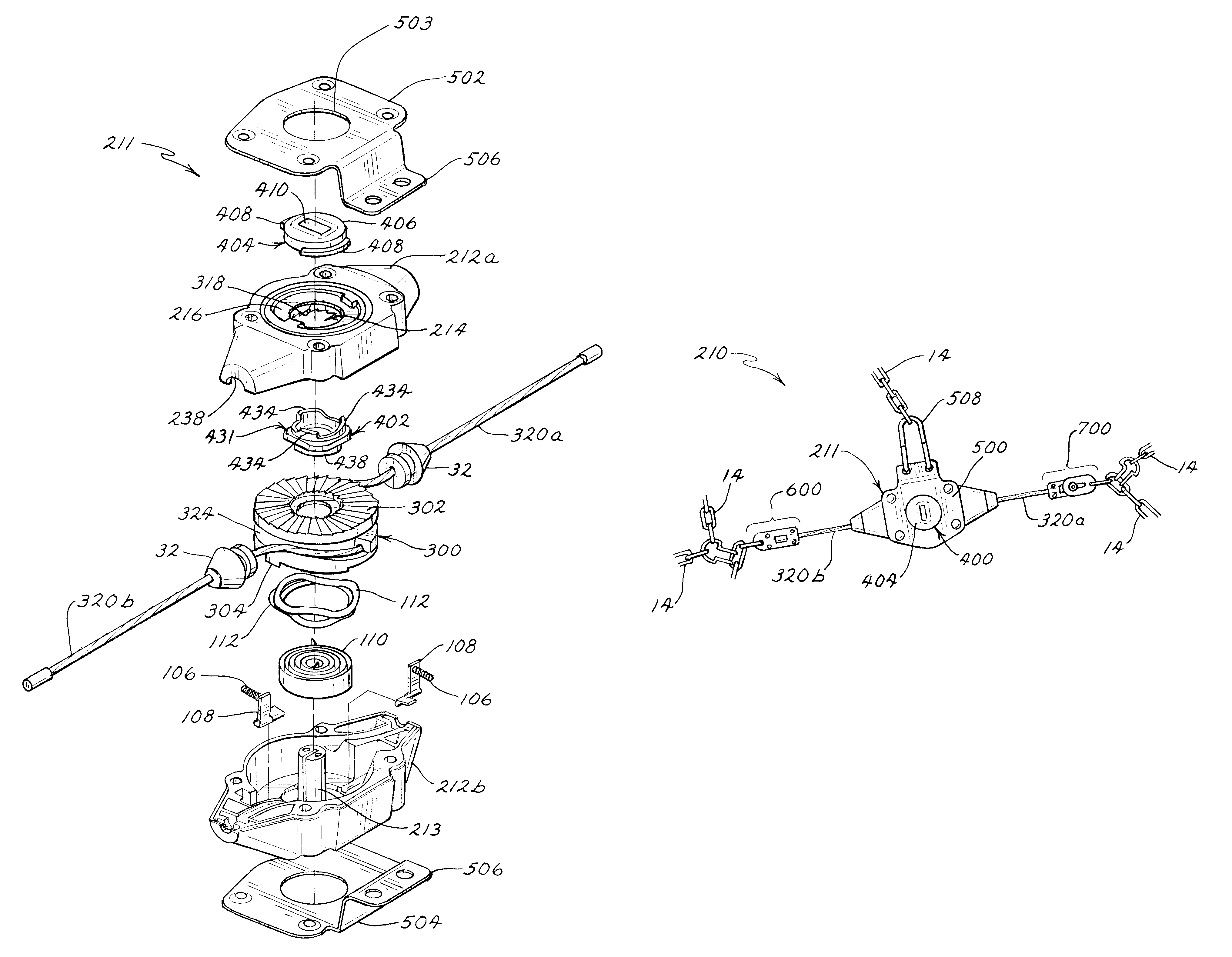
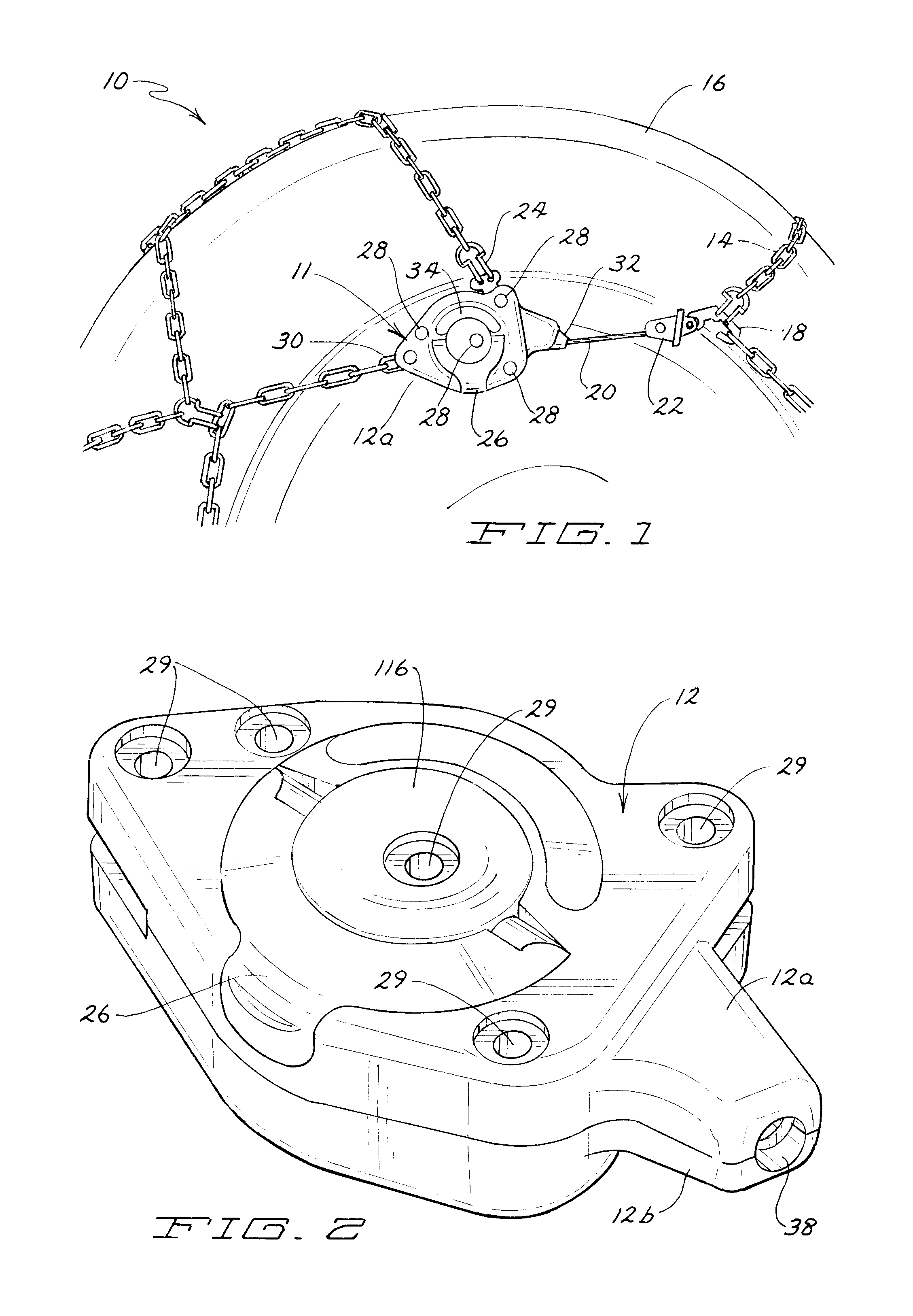
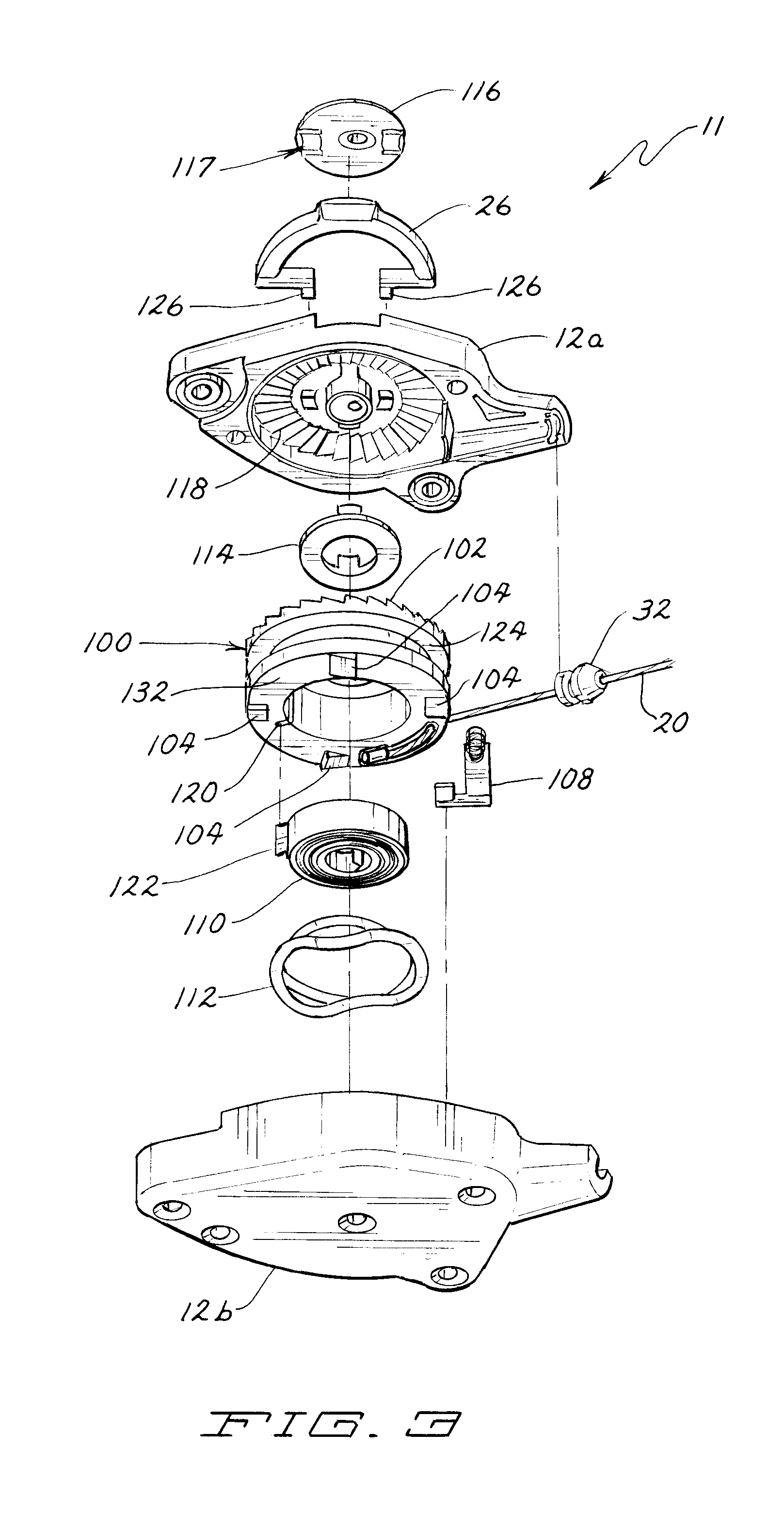
[0047]Various embodiments of the present invention are illustrated in FIGS. 1-23. FIG. 1 is a perspective view of a self-tightening snow chain 10 of the present invention in use on a wheel 16 (partially shown). The self-tightening snow chain 10 comprises of a snow chain 14 and a tensioning device 11. Referring now also to FIGS. 2 and 3, the tensioning device 11 has a housing 12 including a housing top 12a, an actuating lever 26, a grommet 32, and a cord 20 extending through grommet 32 and connected to a hook 18 with a first connection member 22. The hook 18 connects to the chain 14 of the self-tightening snow chain 10, to supply tension to the chain 14. In this embodiment, there is a second connection point 24 and third connection point 30 where parts of the snow chain 14 are secured to the housing 12. Rivets 28 are placed through rivet receiving openings or recesses 29 to secure the housing top 12a to the housing bottom 12b, although any other fasteners such as threaded screws, bol...


PUM


Abstract

Self-tightening traction assemblies or snow chains having tensioning devices that can be used with snow chains for attachment to a vehicle wheel to provide traction. The preferred tensioning device including a housing having a top including a set of housing teeth, a bottom and at least one aperture; an actuator interconnected to the housing; a ratchet spool within the housing having a set of ratchet teeth that mate with the housing teeth and a channel between upper and under surfaces to receive at least one cord that is interconnected with the ratchet spool; a tension spring that places a bias on the ratchet spool toward a wind-up direction; and a wave spring. Preferred embodiments include a bracket that can secure the actuator to the housing and provide strength to the tensioning device. The tensioning devices of the present invention can be utilized in a variety of applications not limited to self-tightening snow chains.

Description

RELATED APPLICATIONS[0001]This application is a continuation-in-part of application Ser. No. 11 / 670,844, filed on Feb. 2, 2007, entitled “Self-Tightening Snow Chain and Methods of Use,” and published as U.S. Publication No. 2007 / 0199635 A1 on Aug. 30, 2007, which application claims priority to U.S. Provisional Application 60 / 765,346, filed on Feb. 2, 2006, and each of which are hereby incorporated by reference.FIELD OF THE INVENTION[0002]The present invention relates generally to self-tightening snow chains or traction assemblies and tensioning devices for use in such traction assemblies or snow chain devices. Various embodiments relate to self-tightening traction assemblies or snow chains having a tensioning device including a winding device and a tensioning cord. The self-tightening snow chains having a tensioned mode, when secured for use on a wheel of a land vehicle, and a separate extended mode, wherein the tensioning cord, interconnected with the winding device is released to ...

Claims


Application Information

Patent Timeline
Patent Type & Authority Patents(United States)
IPC IPC(8): B60C27/10
CPCB60C27/10Y10T24/2181Y10T24/2183Y10S24/909
Inventor MCCAULEY, JOHN J.STENER, LESTER
Owner PEERLESS CHAIN COMPANY
Why Eureka
Try Eureka