Practical image reconstruction for magnetic resonance imaging

a magnetic resonance imaging and image reconstruction technology, applied in the field of medical imaging, can solve the problems of reducing the quality of images, increasing patient discomfort, and prolonging the scan time of patients, and achieve the effect of accelerating the iterative solution process

Active Publication Date: 2011-03-08
SIEMENS HEALTHCARE GMBH
View PDF6 Cites 8 Cited by
  • Summary
  • Abstract
  • Description
  • Claims
  • Application Information

AI Technical Summary

Problems solved by technology

If the data acquisition time is increased, however, the patient is subjected to a longer scan time, which increases patient discomfort.
In some instances, long scan times may actually degrade image quality because of movement of the region of interest during the scan.
Recording a large number of samples, however, has disadvantages.
This will, however, often lead to reduced signal-to-noise ratio (SNR) and to image degradation.
Various techniques have been developed to enhance the image quality reconstructed from under-sampled data, but they require extended computational time and high memory usage.

Method used


Image

  • Practical image reconstruction for magnetic resonance imaging
  • Practical image reconstruction for magnetic resonance imaging
  • Practical image reconstruction for magnetic resonance imaging

Examples


Embodiment Construction

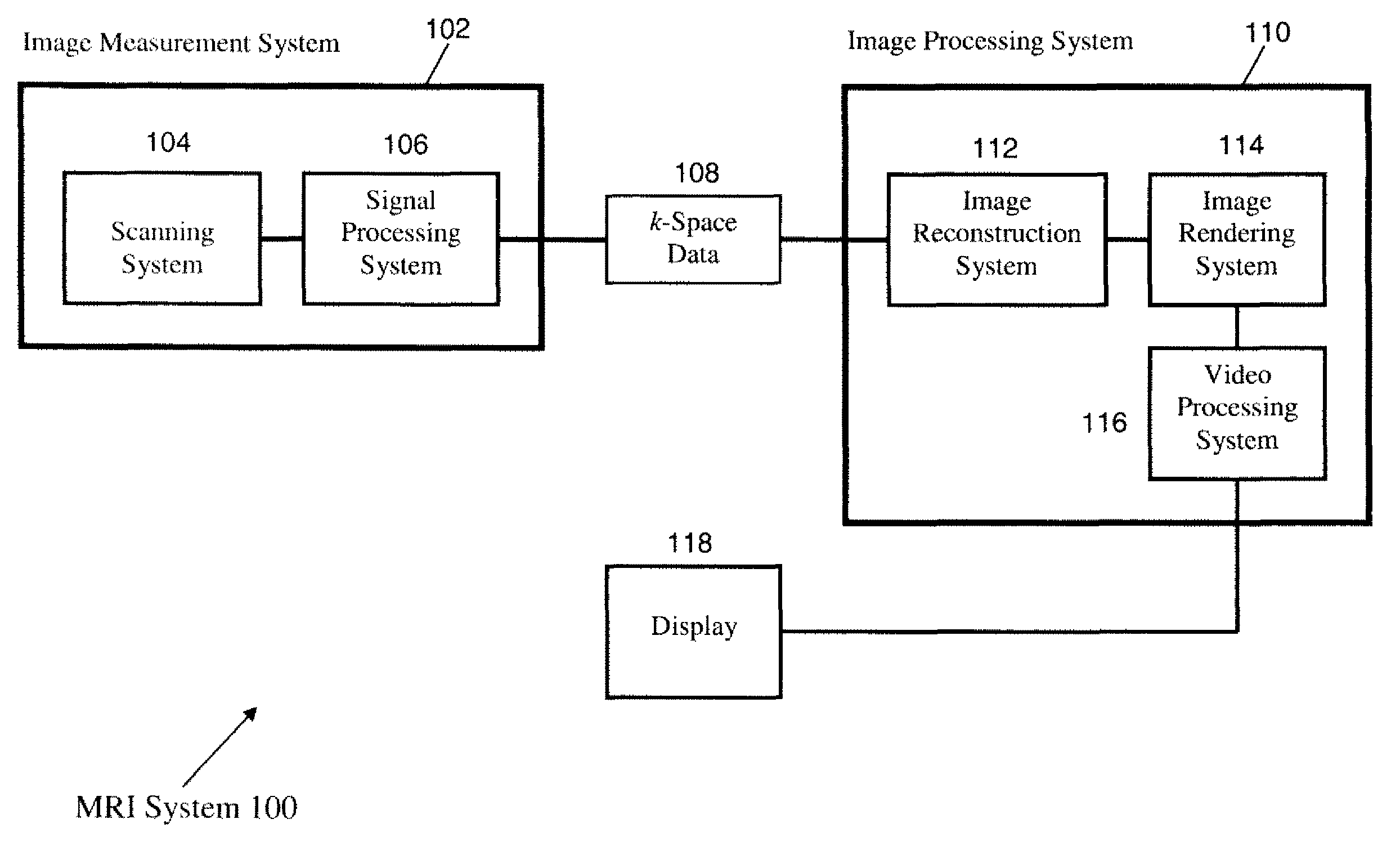
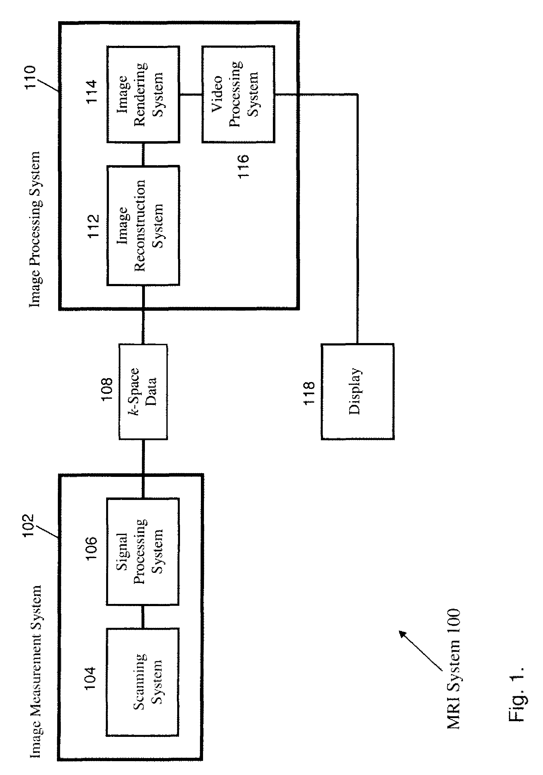
[0010]FIG. 1 shows a high-level schematic of the functional architecture of a representative imaging system. In the example shown in FIG. 1, the imaging system is MRI system 100. Embodiments apply to other modalities. MRI system 100 comprises image measurement system 102, image processing system 110, and display 118. Image measurement system 102 may include scanning system 104 and signal processing system 106. Scanning system 104 includes the MRI scanner and associated instrumentation and software. The output of scanning system 104 are radio-frequency (RF) signals which are fed into signal processing system 106. Signal processing system 106 includes hardware and software which converts the RF signals to k-space data 108, which is discussed further below.

[0011]The k-space data 108 is then fed into image processing system 110, which may include image reconstruction system 112, image rendering system 114, and video processing system 116. Image reconstruction system 112, further discuss...


PUM


Abstract

A set of image-space data is reconstructed from a set of k-space data. The set of image-space data is generated by minimizing a cost functional by an iterative non-linear conjugate gradient process. The iterative process may be accelerated by introducing k-space weighting to the cost functional. With proper choice of k-space weighting, a block-Toeplitz matrix is generated which permits use of Fast Fourier Transform techniques. An image is rendered from the set of image-space data.

Description

[0001]This application claims the benefit of U.S. Provisional Application No. 60 / 864,189 filed Nov. 3, 2006, which is incorporated herein by reference.BACKGROUND OF THE INVENTION[0002]The present invention relates generally to medical imaging, and more particularly to iterative reconstruction of images.[0003]Magnetic Resonance Imaging (MARI) has become a well-established medical diagnostic tool for imaging structures within the body of a patient. Image quality may be characterized by a host of parameters, including resolution, field of view, contrast, edge definition, and artifacts (for example, ghosts and streaks). Under a broad range of conditions, image quality improves with increasing data acquisition time. If the data acquisition time is increased, however, the patient is subjected to a longer scan time, which increases patient discomfort. In some instances, long scan times may actually degrade image quality because of movement of the region of interest during the scan. Short s...

Claims


Application Information

Patent Timeline
Patent Type & Authority Patents(United States)
IPC IPC(8): G06K9/00A61B5/05
CPCG01R33/4824G01R33/56G01R33/5608
Inventor CHANG, TI-CHIUNSONG, JIAYUFANG, TONGSPEIER, PETERMULLER, EDGAR
Owner SIEMENS HEALTHCARE GMBH
Why Eureka
Try Eureka