Cardiac motion tracking using cine harmonic phase (HARP) magnetic resonance imaging

a magnetic resonance imaging and cine harmonic phase technology, applied in the field of measuring heart motion using magnetic resonance imaging, can solve the problems of low signal-to-noise ratio, inability to automatically analyze planar tagging images, and inability to automate approaches

Inactive Publication Date: 2005-05-10
THE JOHN HOPKINS UNIV SCHOOL OF MEDICINE
View PDF5 Cites 103 Cited by
  • Summary
  • Abstract
  • Description
  • Claims
  • Application Information

AI Technical Summary

Benefits of technology

[0028]It is a further object of the present invention wherein angle images may be employed to make such computations automatically and rapidly.
[0029]It is yet another object of the present invention to produce angle images directly from the Fourier data without requiring production of conventional magnetic resonance images.

Problems solved by technology

These approaches are not automated, as they require some manual intervention.
One of the problems with these two approaches is that planar tagging images cannot be accurately analyzed automatically.
Phase contrast images, while capable of being analyzed automatically, tend to have a low signal-to-noise ratio leading to unacceptable results.
In spite of the successful scientific efforts, tagged MRI has been slow to enter into routine clinical use because of long imaging and post processing times, inadequate access to patients during imaging and lack of understanding of MR processing benefits by clinicians and their associates.

Method used


Image

  • Cardiac motion tracking using cine harmonic phase (HARP) magnetic resonance imaging
  • Cardiac motion tracking using cine harmonic phase (HARP) magnetic resonance imaging
  • Cardiac motion tracking using cine harmonic phase (HARP) magnetic resonance imaging

Examples


example 1

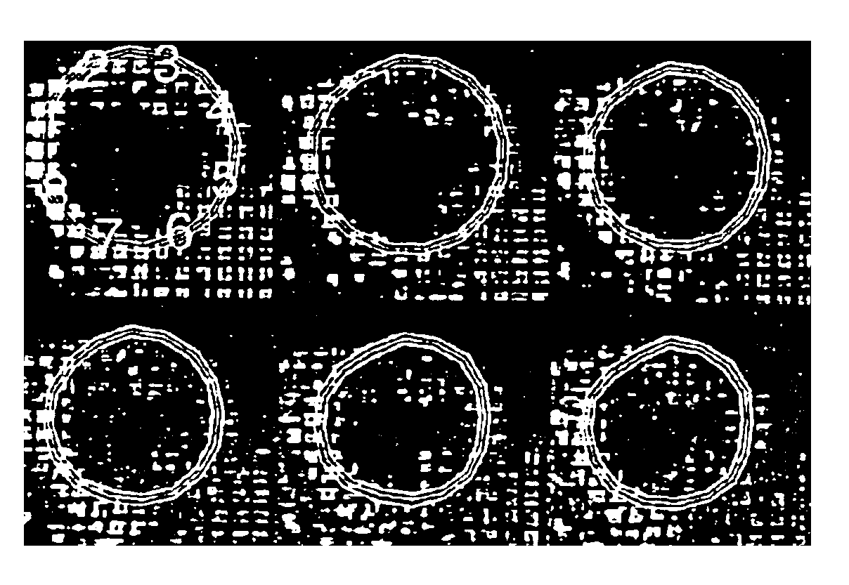
[0123]To demonstrate the capabilities of HARP tracking, a set of tagged images of an electrically paced canine heart were used. These data were previously used in a study of cardiac motion under electrically paced activation using tagged magnetic resonance imaging and analysis techniques. A complete description of the experimental protocol and their results are given in Lima et al., “Segmental motion and deformation of transmurally infarcted myocardium in acute postinfarct period.” Am. J. Physiol., 268(3):H1304-12, 1995. Although the present results yield only apparent motion and strain on a single cross-section rather than giving a complete 3-D description, the results obtained here are very nearly the same as those in Lima et al., but are generated in only a fraction of the time. This provides the benefit of accurate, rapid results through use of the methods of the present invention.

[0124]A pacing lead was placed in the left ventricular basal free wall of a canine heart. Magnetic ...

example 2

[0131]This example involves the use of HARP tracking of the cardiac motion of a normal human male volunteer age 27 undergoing a dobutamine-induced (5 μg / kg / min) cardiac stress. This example includes the very rapid motion of this heart under dobutamine stress and the use of HARP refinement to correct incorrectly tracked points.

[0132]The images were acquired on the same magnet using the same basic imaging protocol as in the canine studies described hereinabove. SPAMM tags were generated at end-diastole to achieve saturation planes orthogonal to the image plane separated by 7 mm. Two sets of images with vertical and horizontal tags were acquired in separate breath-holds. Four slices were acquired, but only the midwall-basal slice is used in this example. Scanner settings were as follows: field of view 36-cm, tag separation 7-mm, 8-mm slice thickness, TR=6.5-ms, E=2.3-ms, 15° tip angle, 256×160 image matrix, 5 phase-encoded views per movie frame.

[0133]FIG. 16(a) shows the resulting hori...


PUM


Abstract

The present invention relates to a method of measuring motion of an object such as a heart by magnetic resonance imaging. A pulse sequence is applied to spatially modulate a region of interest of the object and at least one first spectral peak is acquired from the Fourier domain of the spatially modulated object. The inverse Fourier transform information of the acquired first spectral-peaks is computed and a computed first harmonic phase image is determined from each spectral peak. The process is repeated to create a second harmonic phase image from each second spectral peak and the strain is determined from the first and second harmonic phase images. In a preferred embodiment, the method is employed to determine strain within the myocardium and to determine change in position of a point at two different times which may result in an increased distance or reduced distance. The method may be employed to determine the path of motion of a point through a sequence of tag images depicting movement of the heart. The method may be employed to determine circumferential strain and radial strain.

Description

CROSS REFERENCE TO RELATED APPLICATION[0001]This application claims the benefit of U.S. Provisional Application Serial No. 60 / 130,595, filed Apr. 22, 1999.GOVERNMENT SUPPORT[0002]The present invention was supported at least in part by NIH Grant No. R29 HL47405 and NSF Grant No. MIP93-50336.BACKGROUND OF THE INVENTION[0003]1. Field of the Invention[0004]The present invention relates to the measurement of heart motion employing magnetic resonance imaging and, more specifically, it relates to a process of employing harmonic phase images acquired using magnetic resonance imaging in order to track material points and calculate Lagrangian strain in the heart.[0005]2. Description of the Prior Art[0006]The advantageous use of magnetic resonance imaging wherein a patient or object is placed within a magnetic field with alternating generation of RF pulses and gradient pulses serving to excite nuclei within the area of interest and cause responsive emission of magnetic energy which is picked u...

Claims


Application Information

Patent Timeline
Patent Type & Authority Patents(United States)
IPC IPC(8): A61B5/055G01R33/48G01R33/563
CPCA61B5/055G01R33/563A61B5/7257A61B5/4519Y10S128/922G01R33/56333
Inventor PRINCE, JERRY L.OSMAN, NAEL F.
Owner THE JOHN HOPKINS UNIV SCHOOL OF MEDICINE
Why Eureka
Try Eureka