
System and method for calculating coordinate values of a measuring machine

a technology of coordinate values and measuring machines, applied in pulse manipulation, pulse technique, instruments, etc., can solve problems such as devices affecting the accuracy and speed of measuring prototypes

Inactive Publication Date: 2011-03-08
HONG FU JIN PRECISION IND (SHENZHEN) CO LTD +1
View PDF0 Cites 0 Cited by
  • Summary
  • Abstract
  • Description
  • Claims
  • Application Information

AI Technical Summary

Benefits of technology

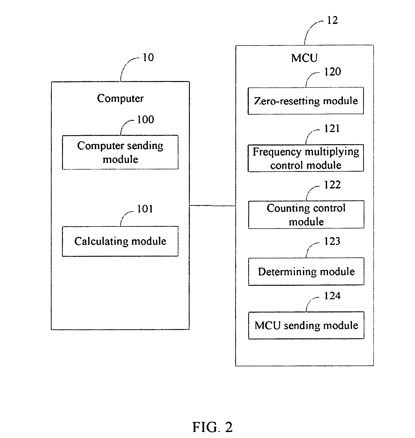
The patent describes a system that uses a raster ruler signal generator to gather signals that are spread over three dimensions of a coordinate axis system. These signals are sent to a computer sending module, which sends an instruction to a micro controller unit (MCU) to gather the signals. The MCU then generates an accumulated number for each signal in each dimension. A calculating module then uses these accumulated numbers and a proportionality factor to calculate the coordinate values of the measuring machine. The technical effect of this system is to provide a more accurate and efficient way to measure and control the position of a machine in three dimensions.

Problems solved by technology

Thus, accuracy and speed of calculating the coordinate value of a prototype device affects an accuracy and a speed of measuring the prototype.

Method used


Image

  • System and method for calculating coordinate values of a measuring machine
  • System and method for calculating coordinate values of a measuring machine
  • System and method for calculating coordinate values of a measuring machine

Examples


Embodiment Construction

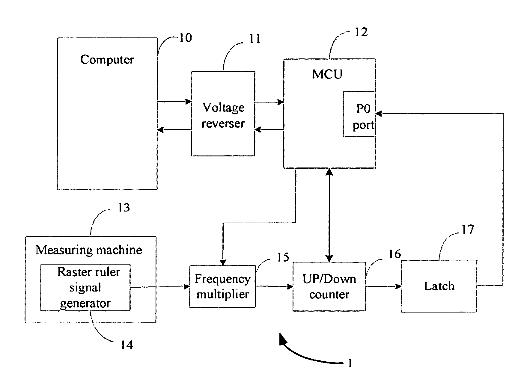
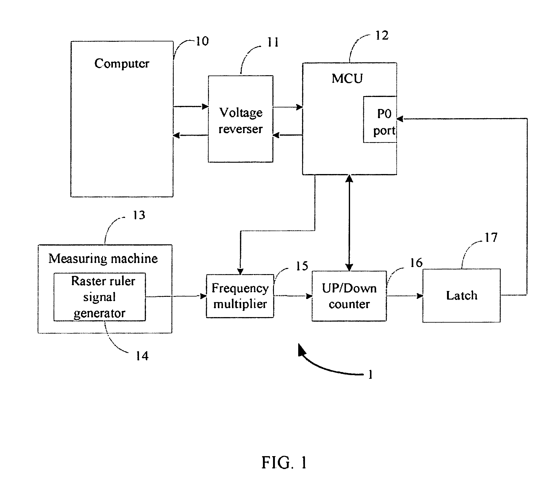
[0011]FIG. 1 is a block diagram of one embodiment of a system 1 for calculating coordinate values of a measuring machine 13. The system 1 is typically implemented by a computer 10 and a micro controller unit (MCU) 12. The MCU 12 may communicate with the computer 10 via a voltage reverser 11. The MCU 12 further communicates with a frequency multiplier 15, an up / down counter 16 and a latch 17. The frequency multiplier 15 connects with a raster ruler signal generator 14 which is installed on the measuring machine 13.

[0012]The voltage reverser 11 is configured for changing a negative voltage from the computer 10 to a positive voltage to be received by the MCU 12.

[0013]The raster ruler signal generator 14 is configured for generating a plurality of signals in three dimensions when the measuring machine 13 moves. The plurality of signals may be spread over three-dimensions of a coordinate axis system (e.g., X, Y, Z).

[0014]The MCU 12 is configured for gathering the plurality of signals gen...


PUM


Abstract

A method for calculating coordinate values of a measuring machine is provided. The method includes receiving signals in three dimensions from a raster ruler signal generator, identifying a direction of each signal and multiply a frequency of each signal. The method further includes counting each of multiplied signals in each dimension, sending the counted data to the MCU. The method further includes adding the counted data of each of the multiplied signals in each dimension to obtain an accumulated number in each dimension and calculating coordinate values of the measuring machine according to the accumulated number in each dimension and a proportionality factor of the raster ruler signal generator.

Description

BACKGROUND[0001]1. Field of the Invention[0002]Embodiments of the present disclosure relate to systems and methods for generating processing data of a measuring machine, and more particularly to a system and method for calculating coordinate values of a measuring machine.[0003]2. Description of Related Art[0004]A measuring machine, such as a three-dimensional measuring machine or a coordinate measuring machine (CMM), is used for measuring profile and dimensions of a prototype device. During the measuring process, the measuring machine determines parameters in order to measure the profile and dimensions of the prototype, such as a coordinate value of a point on the prototype device. Thus, accuracy and speed of calculating the coordinate value of a prototype device affects an accuracy and a speed of measuring the prototype.[0005]Accordingly, what is needed is a system and method for calculating coordinate values of a measuring machine with an improved accuracy and a higher speed.SUMMA...

Claims


Application Information

Patent Timeline
Patent Type & Authority Patents(United States)
IPC IPC(8): G06F15/00
CPCG01B21/04Y10S367/907
Inventor CHANG, CHIH-KUANGSUN, WEI-QI
Owner HONG FU JIN PRECISION IND (SHENZHEN) CO LTD
Learn More